Introduction
Fusion 360 is a cloud-based 3D modeling, CAD, CAM, CAE, and PCB software platform for professional product design and manufacturing.
Design and engineer products how you want to ensure aesthetics, form, fit, and function.
Engineer, design, and create anything with comprehensive electronics and PCB design tools.
Save time and money and get quality parts out the door faster.
Modeling Showcase
CAD model by Herui Guo (Software: Fusion 360)
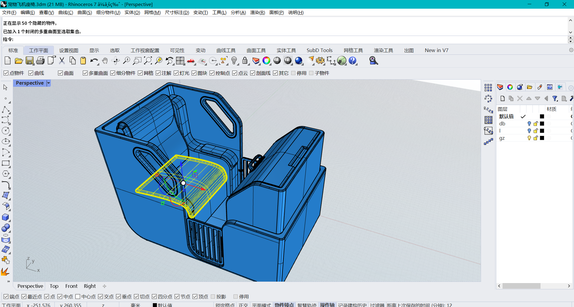
CAD model by Haotian Ying (Software: Rhino)
CAD model by Chenda Zheng (Software: Fusion 360)
CAD model by Liyi Zhang (Software: Fusion 360)
Modeling Procedure
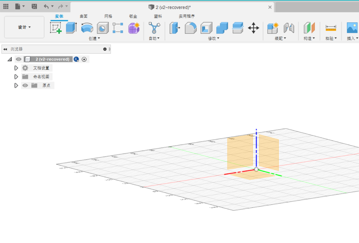
1.Start by opening a folder in Autodesk Fusion360.
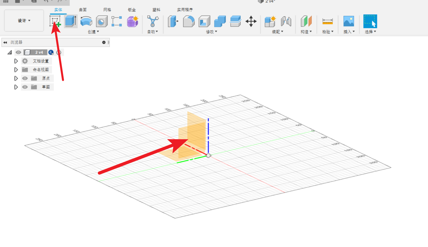
2.Start a sketch.
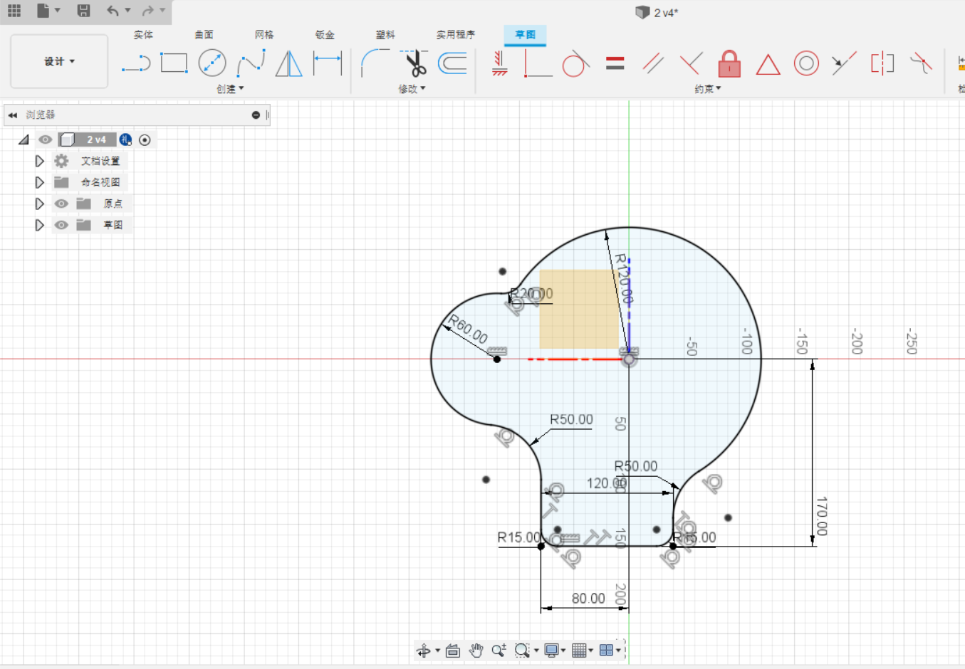
3.Sketch and constrain for preparing.
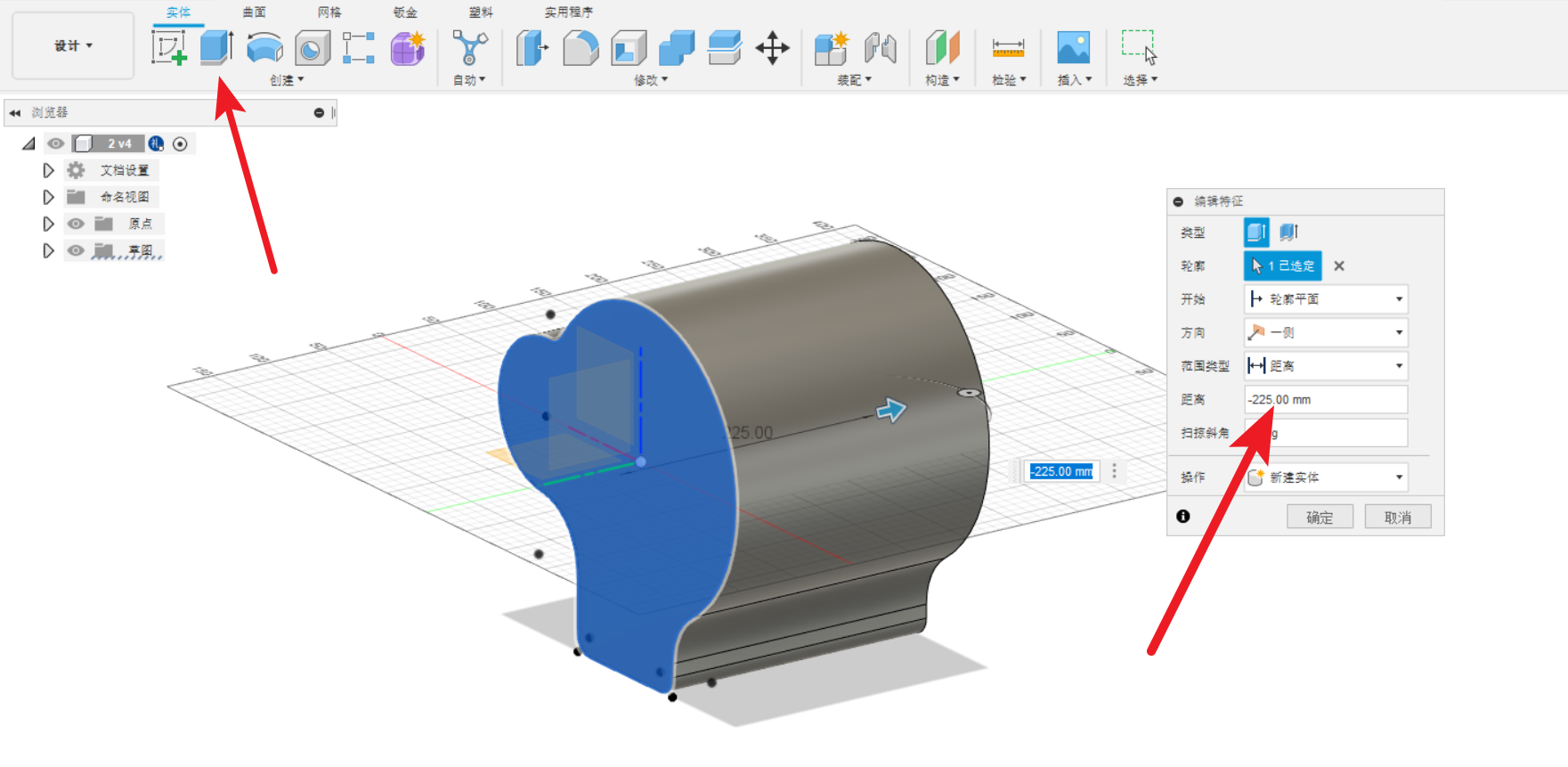
4.Extrude the sketch.
5.The same way to make the screw (use the sketch and extrude).
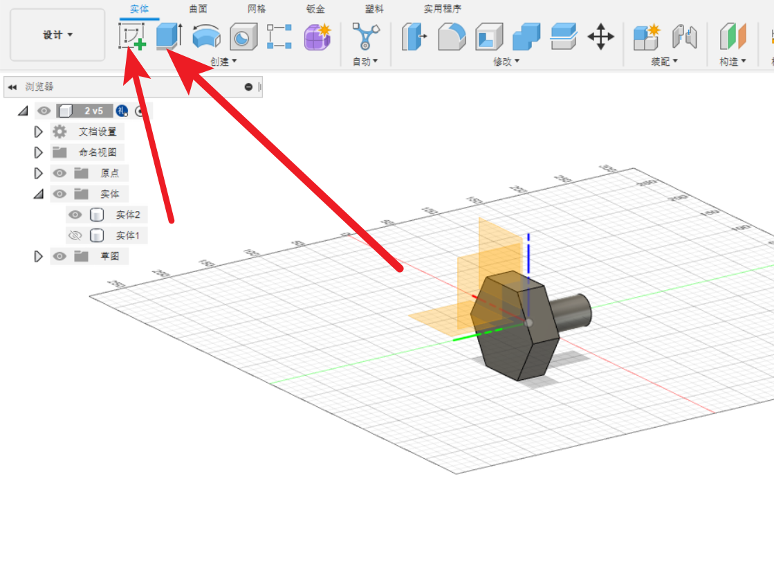
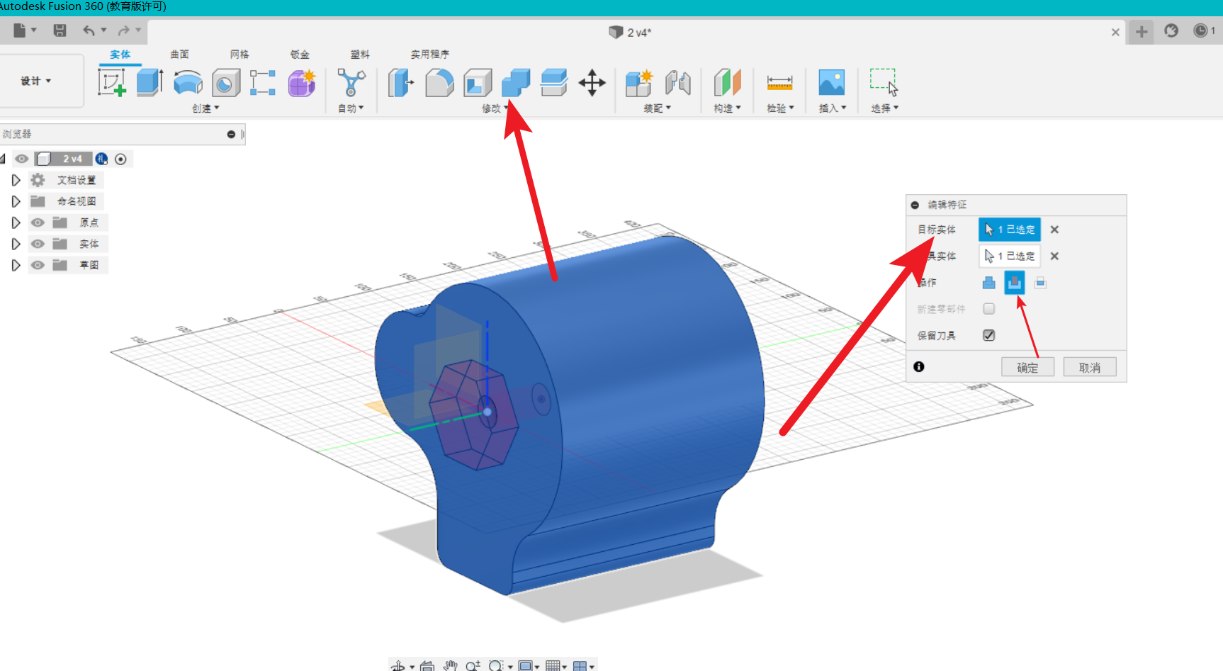
6.Use boolean tool and choose the shear for two entities.
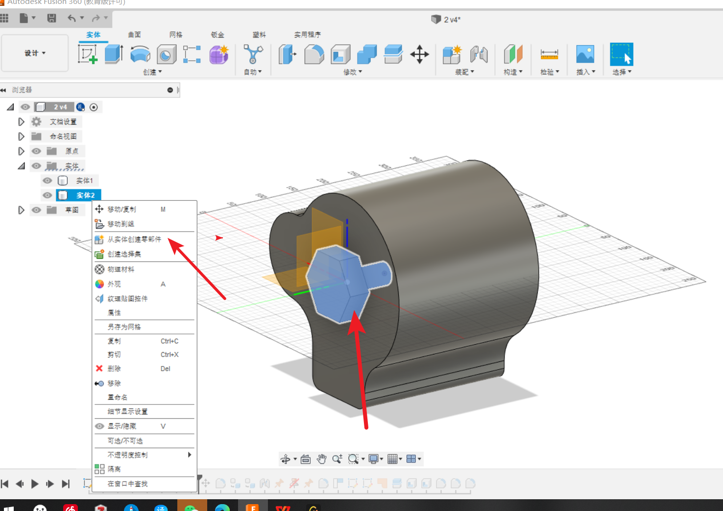
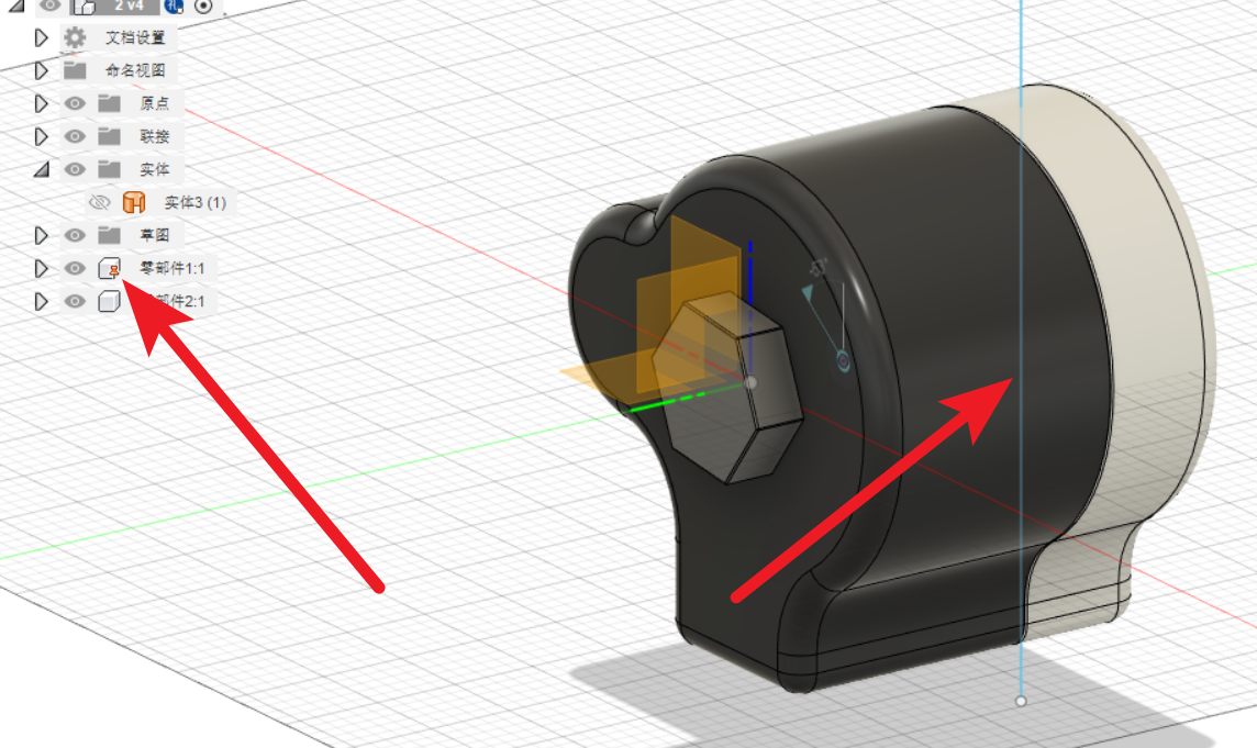
7.Create components by the screw.
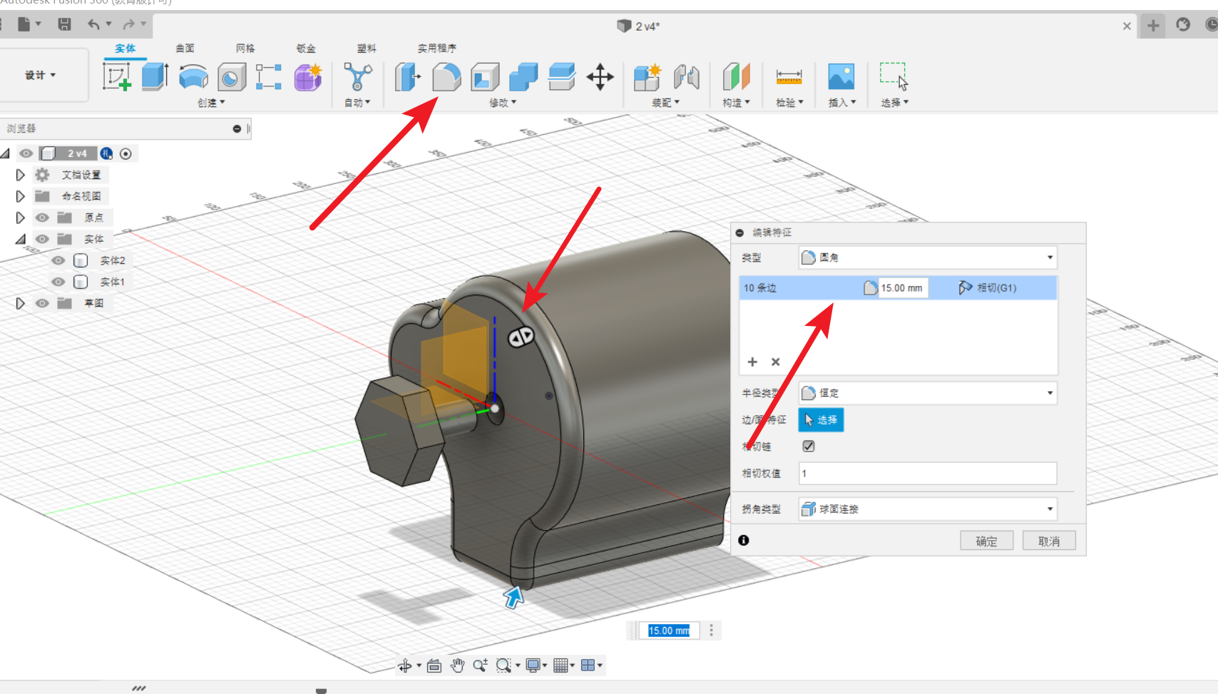
8.Lead a fillet to the main part and create components by it.
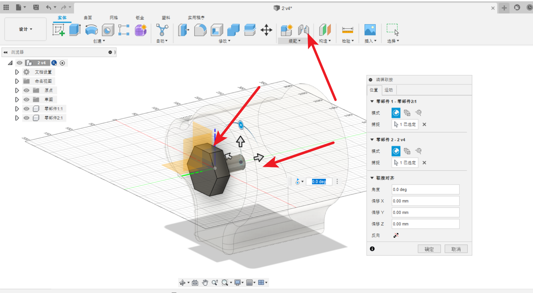
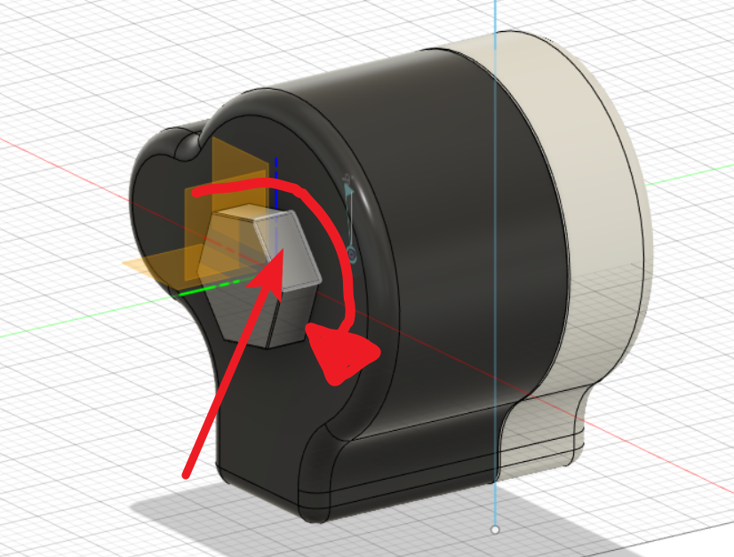
9.Set the assembly relationship between two parts.
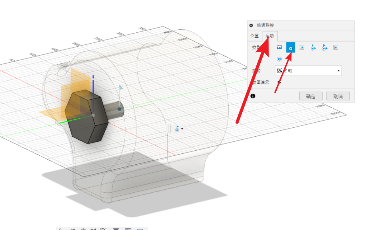
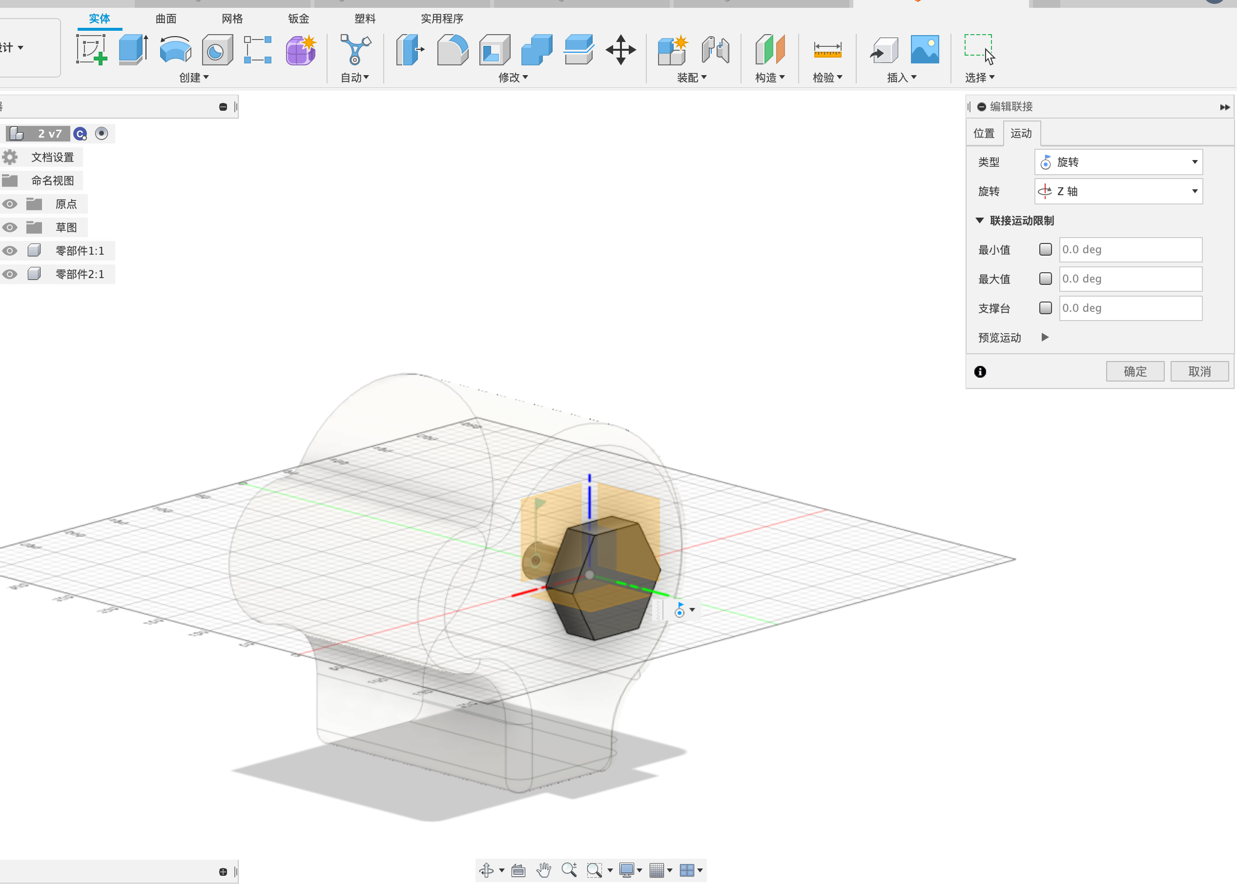
10.Set the motion as rotation on z-axis.
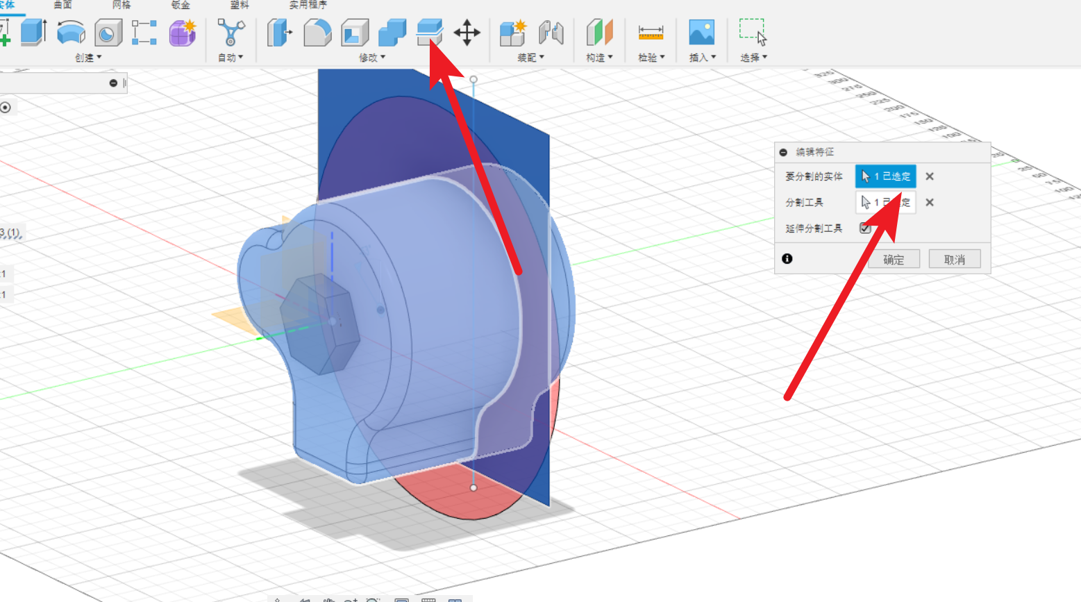
11.Use sketch to make a face.

12.Split component by face.
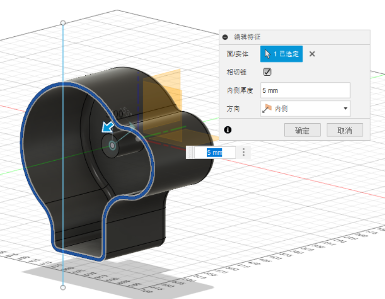
13.Shell the two parts of the component.
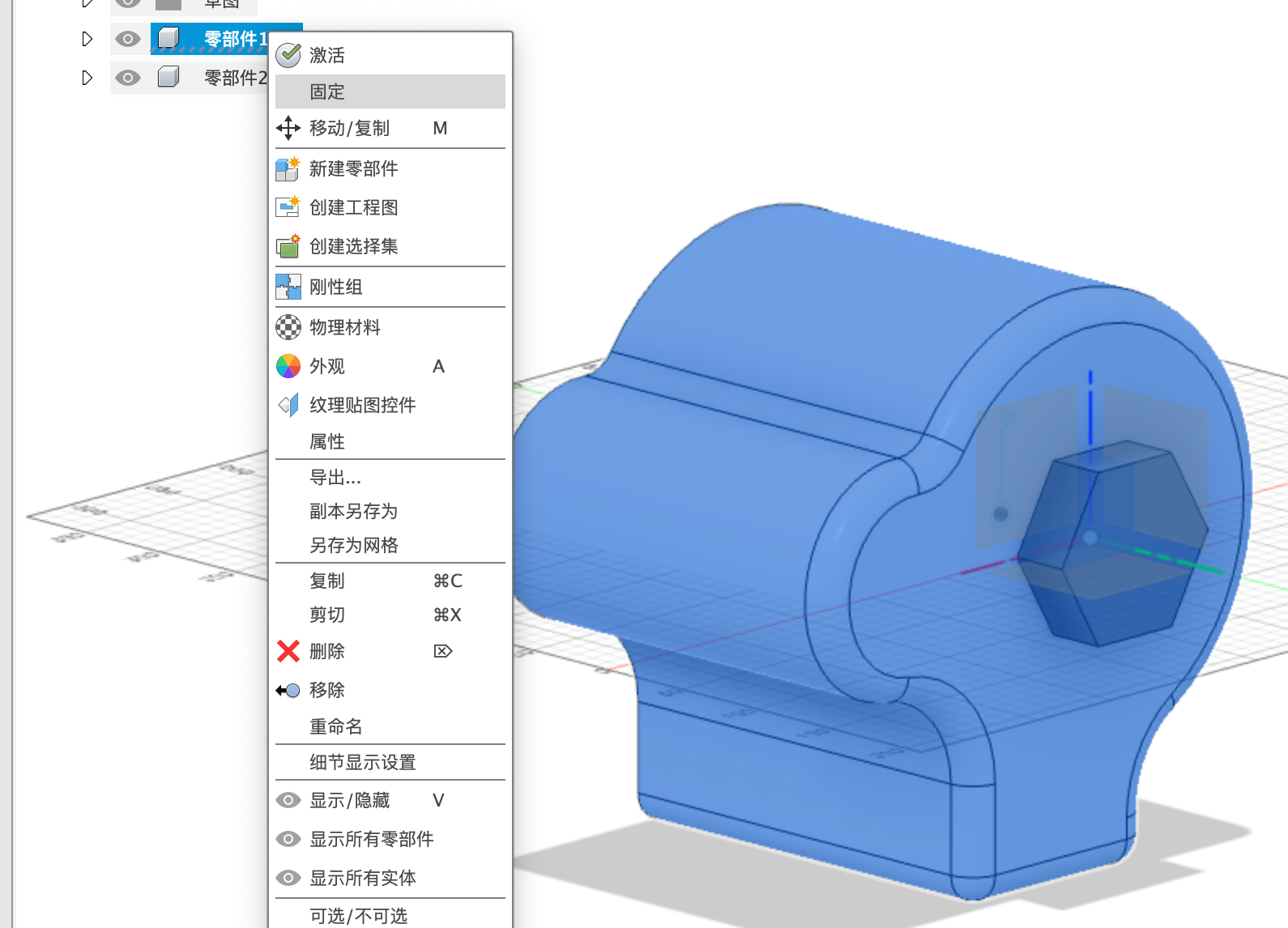
14.Fix the components should be fixed.
15.Use mouse to rotate the component.
The plugin of the Fusion360
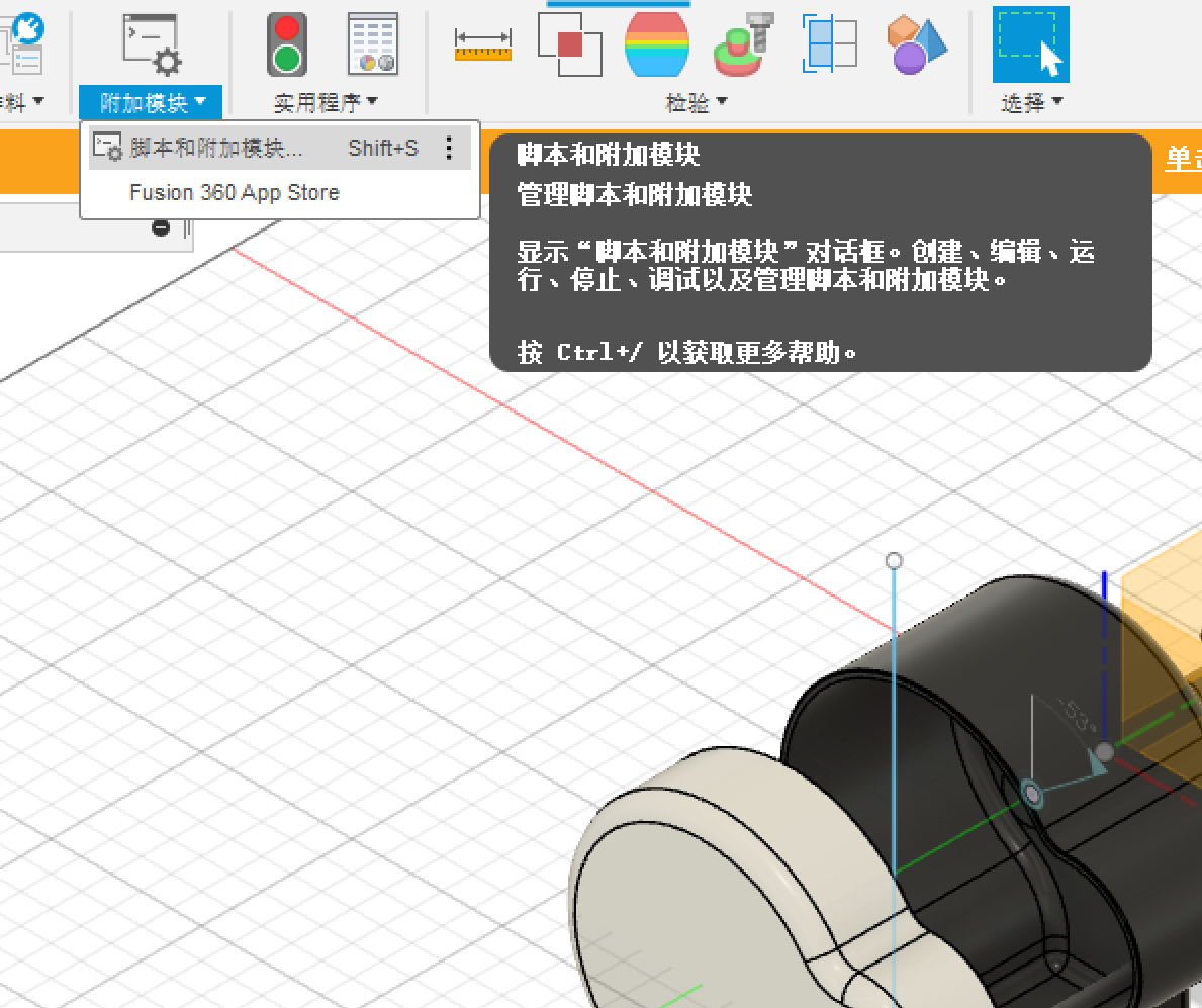
1.Click the plugin buttom.
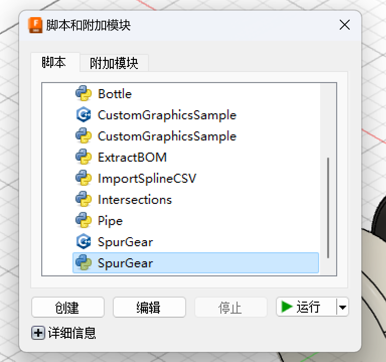
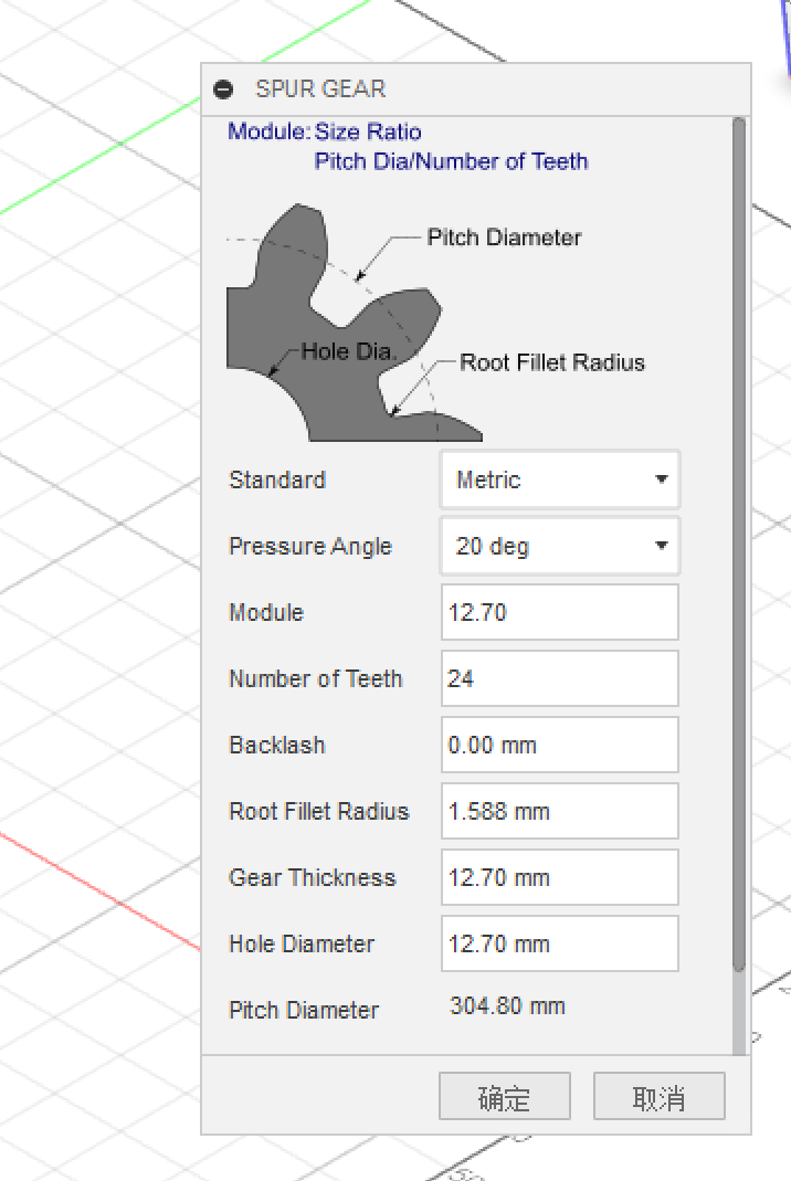
2.Choose the SpurGear as the plugin.
3.Adjust the parameter of the plugin to make a gear.
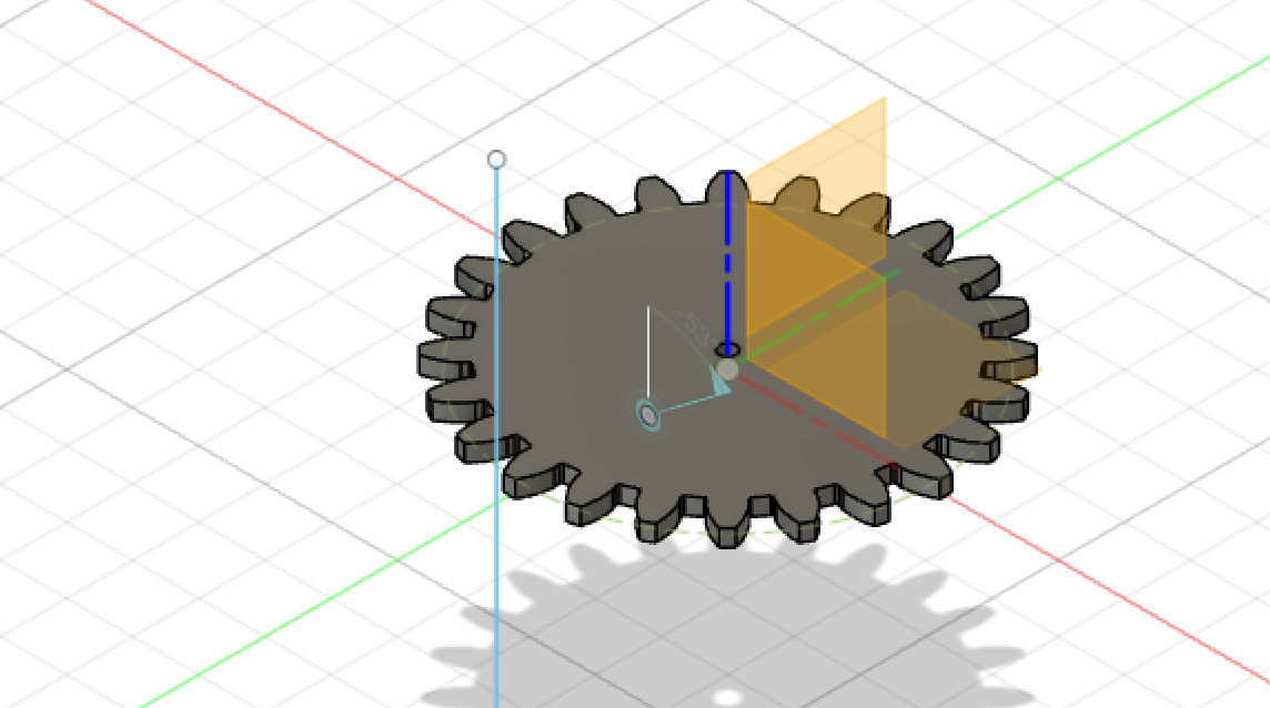
4.The result of the gear made by plugin.
Motion Animation Procedure
1.Select the coupling assembly tool, and select two parts to be assembled.
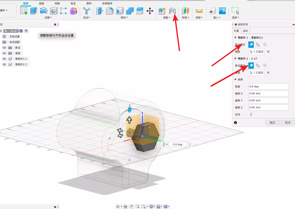
2.Select the motion mode and restrictions between parts.
3.The main parts are fixed and the nut can be rotated.
4.The result of the animation.
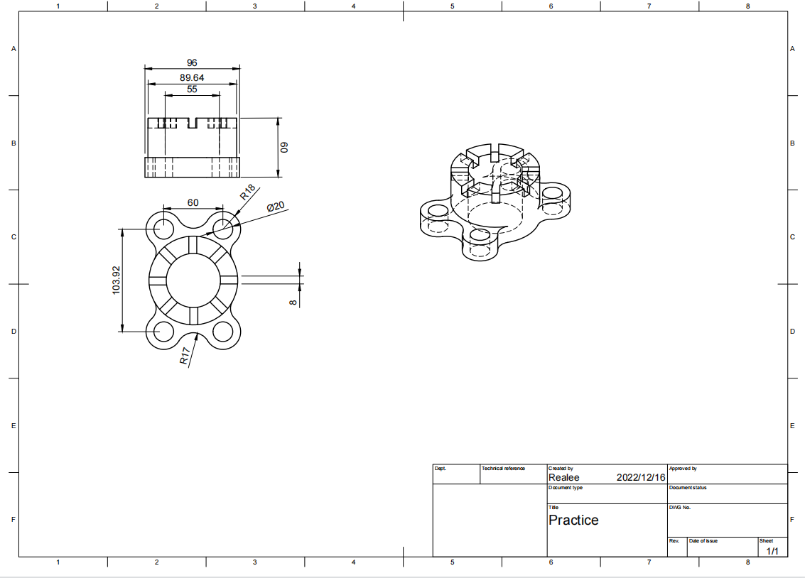
Mechanical drawing
In Autodesk Fusion360, generate mechanical drawing through model.
Other CAD Software
Rhinoceros
Rhinoceros, which has a better NURBS model method than the traditional grid graph model, also has a grid graph model software SubD similar to 3DMax. Its development strategy is to take Rhino as the system software, continue to develop and design technical professional software in various fields, a variety of 3D dyeing software, animation plug-ins, main parameters of solid models and limited change software, so as to gradually improve it. The development trend is to become a universal mapping software. In addition, Rhino's graphics are highly accurate, and can input and output dozens of format files. The models can be produced immediately according to the production, processing or molding of various CNC machine tools. Now they are widely used in architectural planning and design, industrial production and manufacturing, mechanical structure design, scientific research and 3D animation manufacturing. Rhino is capable of creating, writing, analyzing, presenting, 3D rendering, animation and transforming NURBS wireframe, bevel, solid line and irregular graphics grid graph. It will not be limited by precision, complexity, grade or specification.
Creo

Creo Elements (formerly Pro/Engineer), PTC's parametric, integrated 3D CAD/CAM/CAE solution, is used by manufacturers for mechanical engineering, design and manufacturing.
Pro/Engineer was the industry's first rule-based constraint (sometimes called "parametric" or "variational") 3D CAD modeling system.The parametric modeling approach uses parameters, dimensions, features, and relationships to capture intended model behavior. This design approach can be family-based or platform-driven, where the strategy is to use engineering constraints and relationships to quickly optimize the design, or where the resulting geometry may be complex or based upon equations. Creo Elements provides a complete set of design, analysis and manufacturing capabilities on one, integral, scalable platform. These required capabilities include Solid Modeling, Surfacing, Rendering, Data Interoperability, Routed Systems Design, Simulation, Tolerance Analysis, and NC and Tooling Design.
Creo Elements can be used to create a complete 3D digital model of manufactured goods. The models consist of 2D and 3D solid model data which can also be used downstream in finite element analysis, rapid prototyping, tooling design, and CNC manufacturing. All data are associative and interchangeable between the CAD, CAE and CAM modules without conversion. A product and its entire bill of materials (BOM) can be modeled accurately with fully associative engineering drawings, and revision control information. The associativity functionality in Creo Elements enables users to make changes in the design at any time during the product development process and automatically update the end products. This capability enables concurrent engineering design, analysis and manufacturing engineers working in parallel and streamlines product development processes.
About this Post
This post is written by Guo Herui, licensed under CC BY-NC 4.0.