Article Catalog
- Arduino Big Job Experiment (Original Version)
- Arduino Big Work Experiment (Advanced Version)
- Overall Code for Final Experiments
Arduino Big Job Experiment (Original Version)
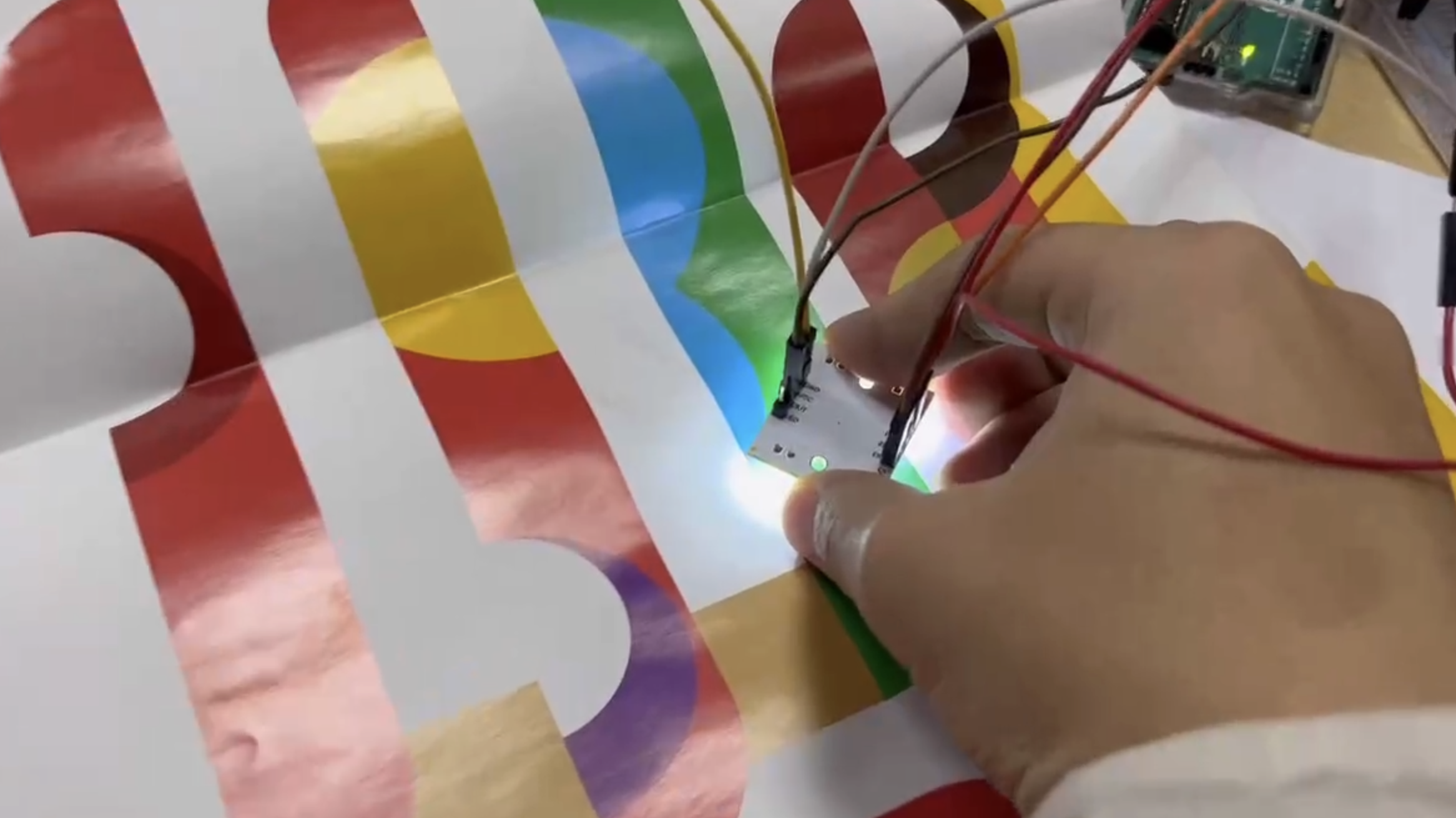
Color sensor
The color sensor is used to identify the painting disc for 1s at a time, and its rgb value corresponds to the corresponding musical style (for example, red is defined as the passionate musical style). Use the switch function to remove the music clip from the sd card.
Code:
Read Color Functions
1 | void readColor() {//从传感器获取数据 |
The color corresponds to the melody function
1 | void decideColor() { |
Calibration Color Function
1 | void calibrate() { |

mp3 module
Store the music corresponding to different colors in the sd card, named 1,2,3,4,5,6. And use the switch statement to call the color in it.
Code:
Play Music Functions
1 | oid playMusic() { |

Steering gear section
The steering gear part uses a 180 degree SG90 motor and a 360 degree SG90 motor, and SG90180 controls the rotation of the rotor arm. The SG90 360 controls the painting to rotate in order to achieve color recognition of the entire disk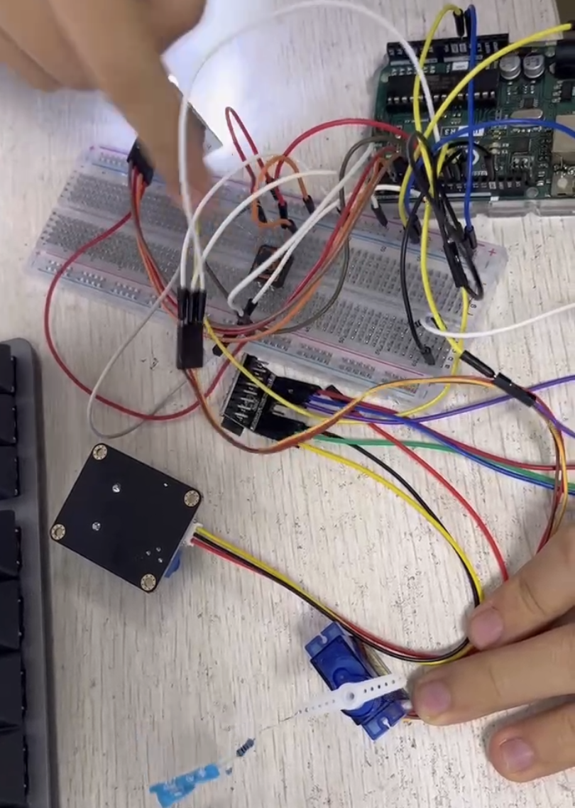
Vocal part
Use the buzzer
Integral code:
1 | #include <SoftwareSerial.h> |
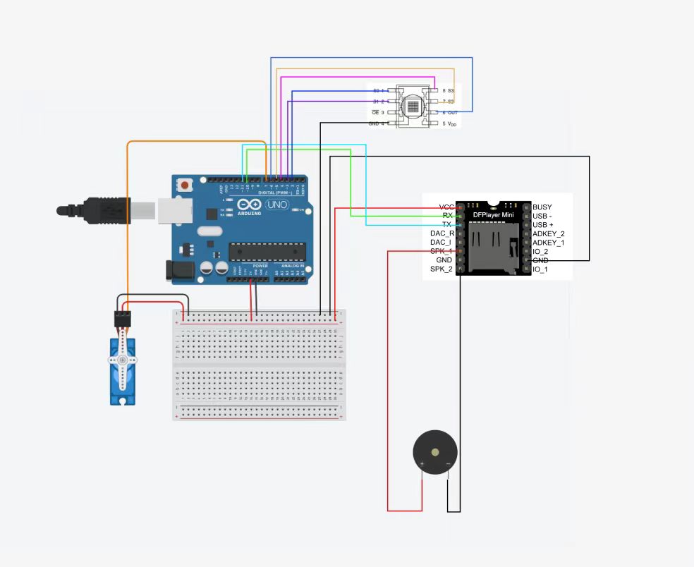
Wiring diagram


Problems encountered:
- The sound quality of the buzzer is not good
- 360 degrees of the steering gear corresponds to the speed, and the rotation of the steering gear cannot be controlled at a constant speed. Even using a for loop can only increase and decrease its speed.
- No switch control, start to rotate when powered on.
- Poor experimental effect
Arduino Big Work Experiment (Advanced Version)
Improvement of the original effect: the color of the painting plate varies with the drawing of different people, and there is randomness. As a result, the melody of the song is confused and the listening feeling is not good. To this end, we decided to replace the song fragments that correspond to different colors with different sound effects (such as tapping, tapping, and drumming). It is applied to the beat of a relatively universal basic bgm, and the recognized delay number corresponds to the number of beats.
Double track implementation
Then use an mp3 module to store bgm.
Improvement of steering gear
Replace the 360-degree steering with a stepper motor
Code:
1 | // 引入Stepper库 |


The switch is triggered
When the switch is pressed and released, the uno controls the rotation of the SG90 servo and the rotation of the stepper motor.
Code:
1 | #include <Servo.h> |
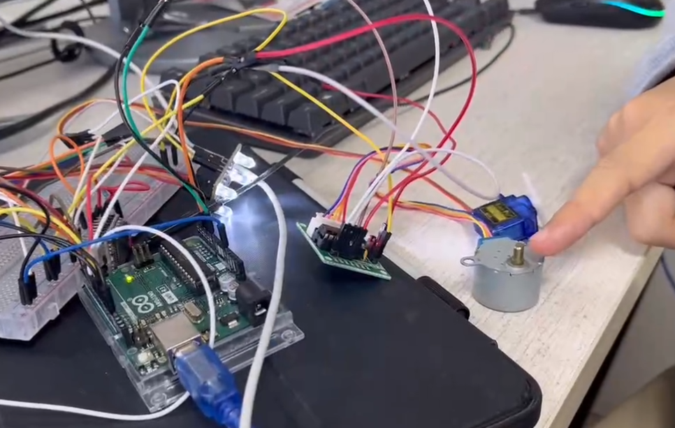
Wiring diagram: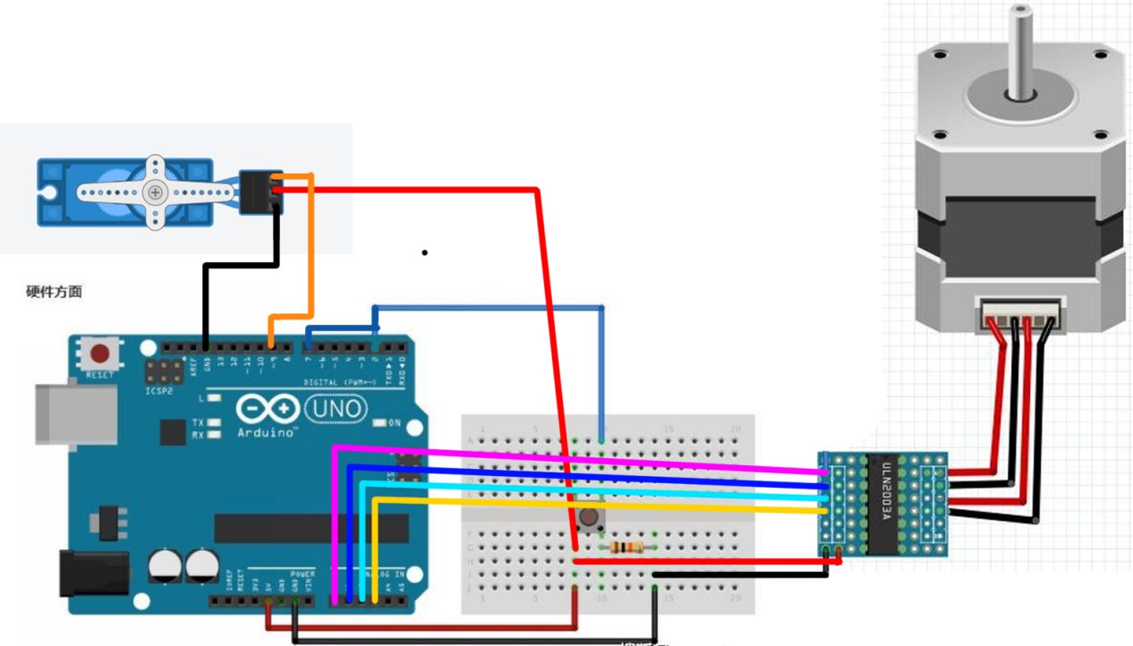
Problem
Uno is not able to control servo servos and stepper motors in parallel, and the two are sequential, and experiments require them to run in parallel.
Ways to improve
Use two UNO boards for control and connect in parallel with switches
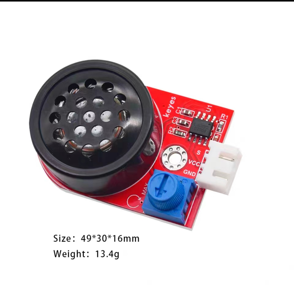
Buzzer replaced with power amplifier module
Precautions
In the previous experiment, the pins of the buzzer were connected to the SPK_1 and SPK_2 ports of the MP3 module. If you want to use the power horn module, you need to connect DAC_R or DAC_I port.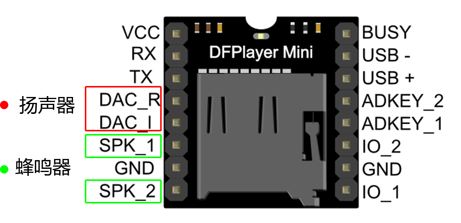
Code:
1 | #include <SoftwareSerial.h> |
Overall Code for Final Experiments
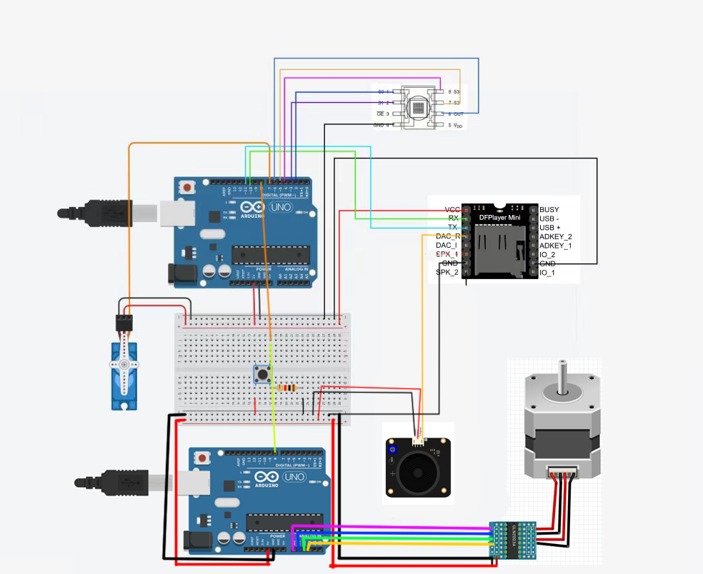
UNO board 1
Code:
1 | #include <SoftwareSerial.h> |
UNO board 2
Code:
1 | #include <Stepper.h> |
Overall Wiring Diagram