The Introduction of Final Project
Interaction Process
1.Design Concept: In the time before ocean pollution, the ocean world was vibrant and colorful. However, as people’s attention towards the ocean gradually decreased and with the current pollution of the ocean, the brilliance of the ocean is slowly dissipating.
Corresponding Interaction Effect: After the device is powered on, the LED strip will first light up 30 LEDs in a flowing manner, then operate in a breathing light mode, symbolizing the vibrant and colorful nature of the ocean. After the breathing light program ends, the LED strip will gradually extinguish in a flowing manner, losing its brightness, which signifies the decreasing attention towards the ocean.
2.Design Concept: The ocean has lost its original colors, and there is a whale stranded on the shore, unable to find its way home. But if we are willing to care for the ocean, it may take some time, but our intentions will be transmitted to the world of the ocean. At that moment, our heartbeat will synchronize with the whale, with the jellyfish, and with the entire ocean. The sea will shimmer again, and the ocean will become vibrant and colorful once more. The sound of the waves echoing in our ears and the gentle sea breeze brushing against our face will bring new vitality to the ocean.
Corresponding Interaction Effect: When the finger touches the heart rate sensor, the sensor receives the values. When the heart rate value reaches the set range, the fan starts first, followed by the MP3 player. The LEDs in the whale blink twice, then the LED strips in both the whale and the jellyfish blink three times, signifying the synchronization of heartbeats. The LED strip first lights up in a random flowing manner, symbolizing the shimmering sea surface. Finally, the LED strip lights up in a breathing light mode, symbolizing the restoration of brightness on the sea surface.
Logic Flowchart
Based on the interaction process and design concept, the logic flowchart of the program’s operation is as shown in the diagram below:
Sensor Introduction
PulseSensor heart rate sensor
(1) Introduction: The pulse sensor is a sensor used to test heart rate. Students, artists, athletes, creators, game or mobile device developers can develop interactive works related to heart rate. The sensor can be worn on the finger or earlobe and can be connected to Arduino via an interconnect cable. It also has an open source app that can display the heart rate as a graph in real time. Essentially, it is an optical heart rate sensor that integrates amplification and noise cancellation circuits. For this final project, the heart rate sensor is used to obtain instantaneous heart rate values. The subsequent program will only be triggered when the heart rate value reaches the value of the conditional function.
(2) Sensor Verification: Before using the sensor, it is necessary to verify whether the sensor can work properly. When purchasing the PulseSensor, the seller will provide corresponding files for verification. However, the problem encountered is that when you do not use the given code, but modify it according to your own experimental requirements, error messages always appear. The solution to this problem will be discussed in detail later. The following code is the verification code for the heart rate sensor and pictures of the verification process.
Code part: (The verification code used here is not the official code provided by the seller, but the relevant code was simplified based on information found independently. The reference link will be attached later.)
1 | |
Pictures of the verification process: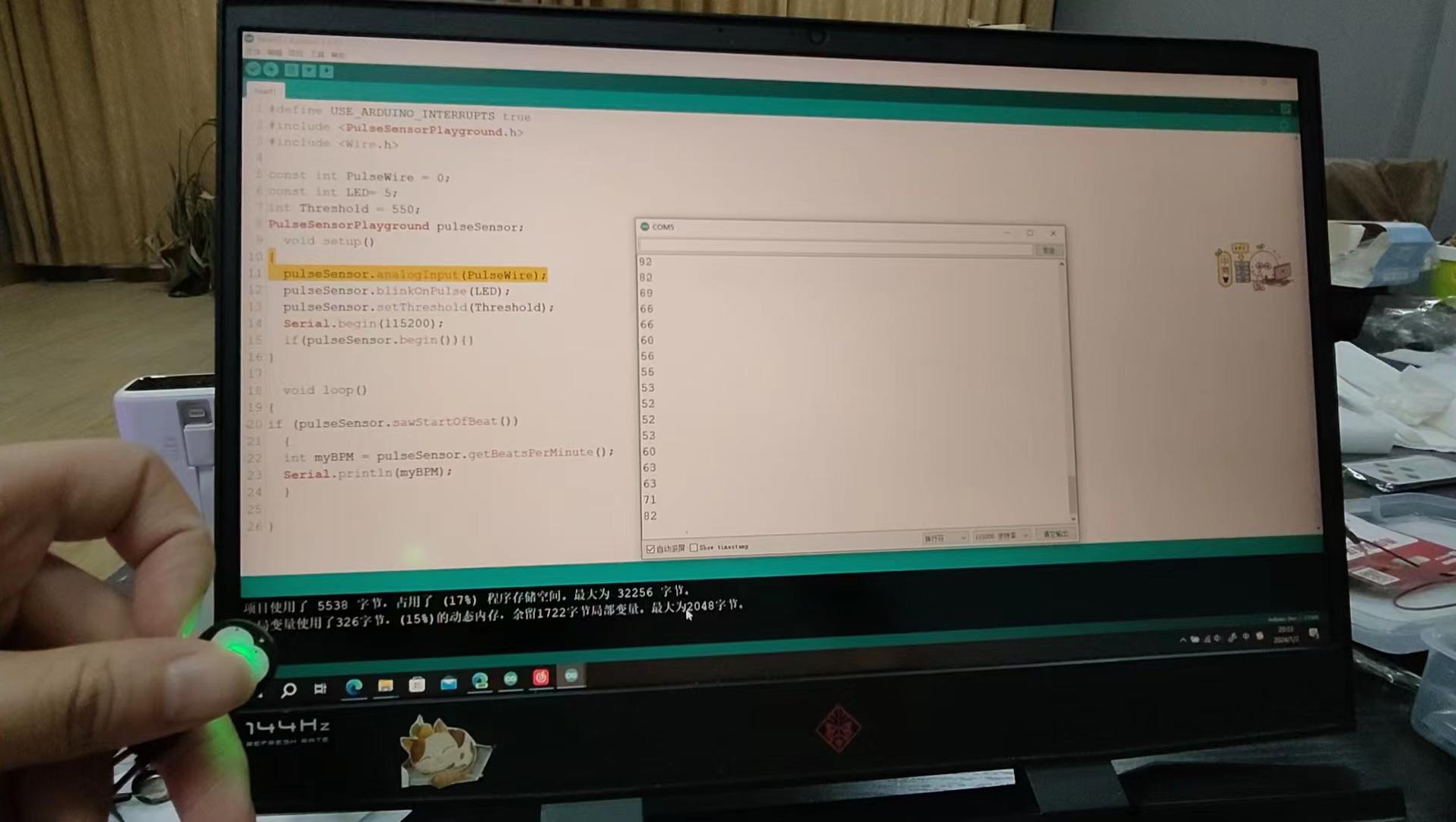
(3) Problems encountered during use: When using the PulseSensor, it is necessary to download the official Arduino PulseSensorPlayground library. Most tutorials only require calling this one library function, but in actual operation, it is often not enough, and there may be errors in the library functions column. In this case, you can add the Wire library to use together. However, even if both of these libraries are used simultaneously during the actual verification process, errors may still occur. After reviewing a lot of information and videos, I finally found a solution. Therefore, if you continue to use the heart rate sensor, it is recommended to use the following three lines of code to ensure the stability of the experiment. As shown in the figure:
2.WS2812B LED Strip
(1) Introduction: The WS2812B LED strip is an intelligent external controlled LED light source that integrates control circuitry and emitting circuitry into one. Its appearance is the same as a 5050 LED bead, with each component being a pixel. Each pixel contains an intelligent digital interface, a data latch signal, shaping and amplification driving circuitry, as well as a high-precision internal oscillator and a programmable constant current control section with a 12V high voltage. This effectively ensures the highly consistent color of the pixel’s light. The data protocol uses a single-line zero-code communication method. After power-on reset, the DIN end of the pixel receives data transmitted from the controller. The first 24-bit data is extracted by the first pixel and sent to the data latch inside the pixel. The remaining data is processed and amplified by the internal shaping circuitry and then forwarded to the DO port to output to the next cascaded pixel. With each transmission through a pixel, the signal decreases by 24 bits. The pixel adopts automatic shaping and forwarding technology, which means that the number of cascaded pixels is not limited by the signal transmission, but only by the requirements of signal transmission speed.
(2) Sensor verification: There are many examples of experiments with WS2812B, and typically the FastLED library is used to drive the LED strip. In the verification process, a simple function was used to verify the breathing light effect of the LED strip.
The verification code is as follows:
1 | |
Pictures of the verification process: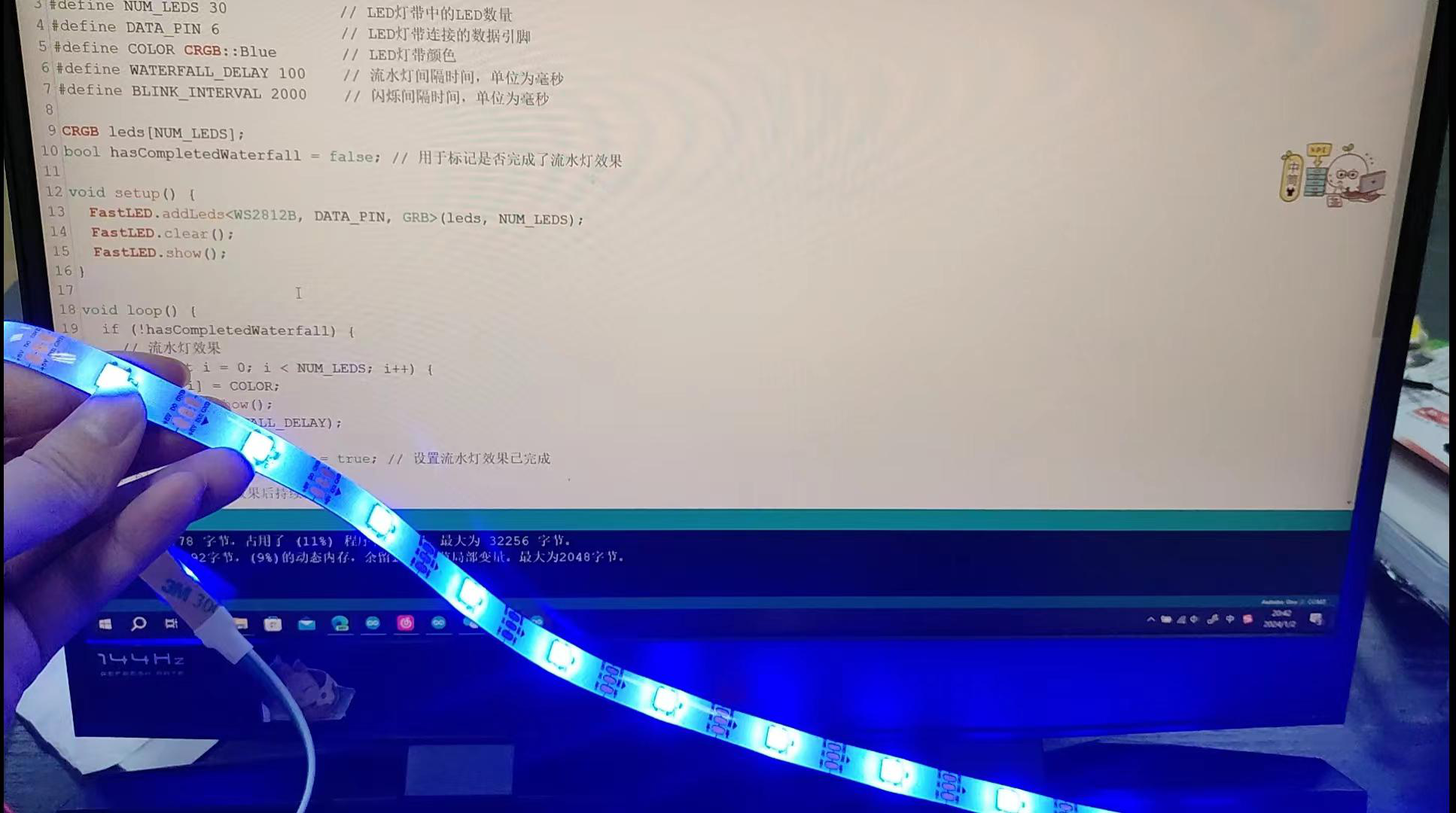
3. DF Player
(1) Introduction: DF Player is a compact and low-cost MP3 module that can be directly connected to a speaker. The module can be used independently with power supply, speaker, and buttons, or controlled through a serial port as a module for Arduino UNO or any other microcontroller with a serial port. The module itself integrates MP3, WAV, and WMA hardware decoding perfectly. The software supports TF card driver and FAT16/FAT32 file systems. By using simple serial commands, you can play specified music and perform other functions, such as how to play music, without the need for complicated low-level operations. It is easy to use, convenient, and reliable.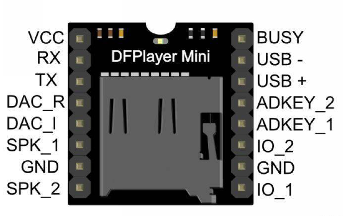
(2) Verification process: The use of DF Player module requires other accessories: an SD card and an external speaker. First, save the required audio files to the SD card, and then trigger the corresponding track by setting the program. Here is a simple verification process that plays the first song on the SD card.
The verification code is as follows:
1 | |
Pictures of the verification process:
(3) Issues during the verification process: First, pay attention to the wiring and pin correspondence. From the diagram above, it can be observed that in this simple experiment, the other end pin of the module is not used. The pin connection should be based on the actual situation. Secondly, similar to the heart rate sensor, there may be issues with library functions. Firstly, DF Player also has an official library function. However, during the process of searching for information, I found two very similar library functions, namely DFPlayer_Mini_Mp3 library and DFRobotDFPlayerMini library. The second library can be downloaded directly in the Arduino IDE. Since I have not actually used the first library and do not know its effect, I have proven that the second library works and used it for this assignment. Additionally, DF Player needs to be used in conjunction with another library. The library function invocation is shown in the figure below:
4.DC Motor Fan
(1) Introduction: It is difficult for Arduino to directly drive a DC motor, so in this experiment, a relay is used to control the DC motor, and an external 1.5V battery is used for power supply.
The principle of the relay is weak current controlling strong current. On the left side, there are three pins: one is the input VCC, one is the ground GCC, and one is the signal IN.
On the right side, there are three pins: NC (normally closed), COM (common), and NO (normally open).
When IN is high, the normally closed terminal is connected to the common terminal; when IN is low, NO-COM is connected.
It should be noted that the relay does not provide power to the pins on the left side. The IN pin of the relay determines which side the switch is attracted to (using the electromagnetic effect). Therefore, in order to achieve the effect of the relay disconnecting/closing, we need to connect NC-COM or NO-COM on the left side to a powered main circuit.
(2) After connecting the motor to the relay and external power supply, the motor can be driven to rotate using the program. The verification code is as follows:
1 | |
Pictures of the verification process:
Explanation of the complete code
(1) The code starts by calling the necessary libraries and defining some parameters.
1 | |
(2) The sensor’s connection pins and related parameters are defined.
1 | |
(3) Sub-functions that will be called later are defined.
1 | |
(4) The LED light and motor pins are set as output mode, and the motor is turned off.
1 | |
(5) DF Player initialization settings are done.
1 | |
(6) Heart rate sensor initialization settings are done.
1 | |
(7) LED strip initialization settings are done. In order to achieve the desired interaction effect, code for creating a flowing light or breathing light effect is added in the SETUP function.
1 | |
(8) In the loop function, data from the heart rate sensor is read, and the heart rate value is checked to see if it reaches the desired threshold.
1 | |
(9) The main code for the desired effects is written as separate sub-functions. It can be observed that many of the same sub-functions are called multiple times in the code. Attempts were made during the experimental process to use a counter in the sub-functions to achieve a blinking effect that occurs 10 times with a single function call. However, the Arduino IDE can only understand relatively simple code, and when too many conditional or loop functions are added, the program may freeze or produce errors, failing to achieve the expected results. Therefore, you will see multiple repeated sub-function calls in the code block.
Below is a screenshot showing part of the main effect code:
1 | |
Finally, here is the complete code for the entire program:
1 | |
Finally, here are the reference cases for our final project:
https://blog.csdn.net/weixin_41659040/article/details/120582966
https://blog.csdn.net/weixin_41659040/article/details/132465032
https://blog.csdn.net/weixin_43031092/article/details/108712833
https://blog.csdn.net/weixin_44887565/article/details/132874517
https://blog.csdn.net/weixin_41659040/article/details/132161843