Second class assignment
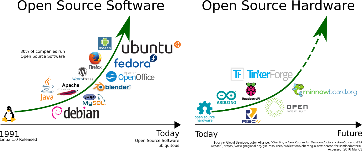
h3>Open Source Hardware


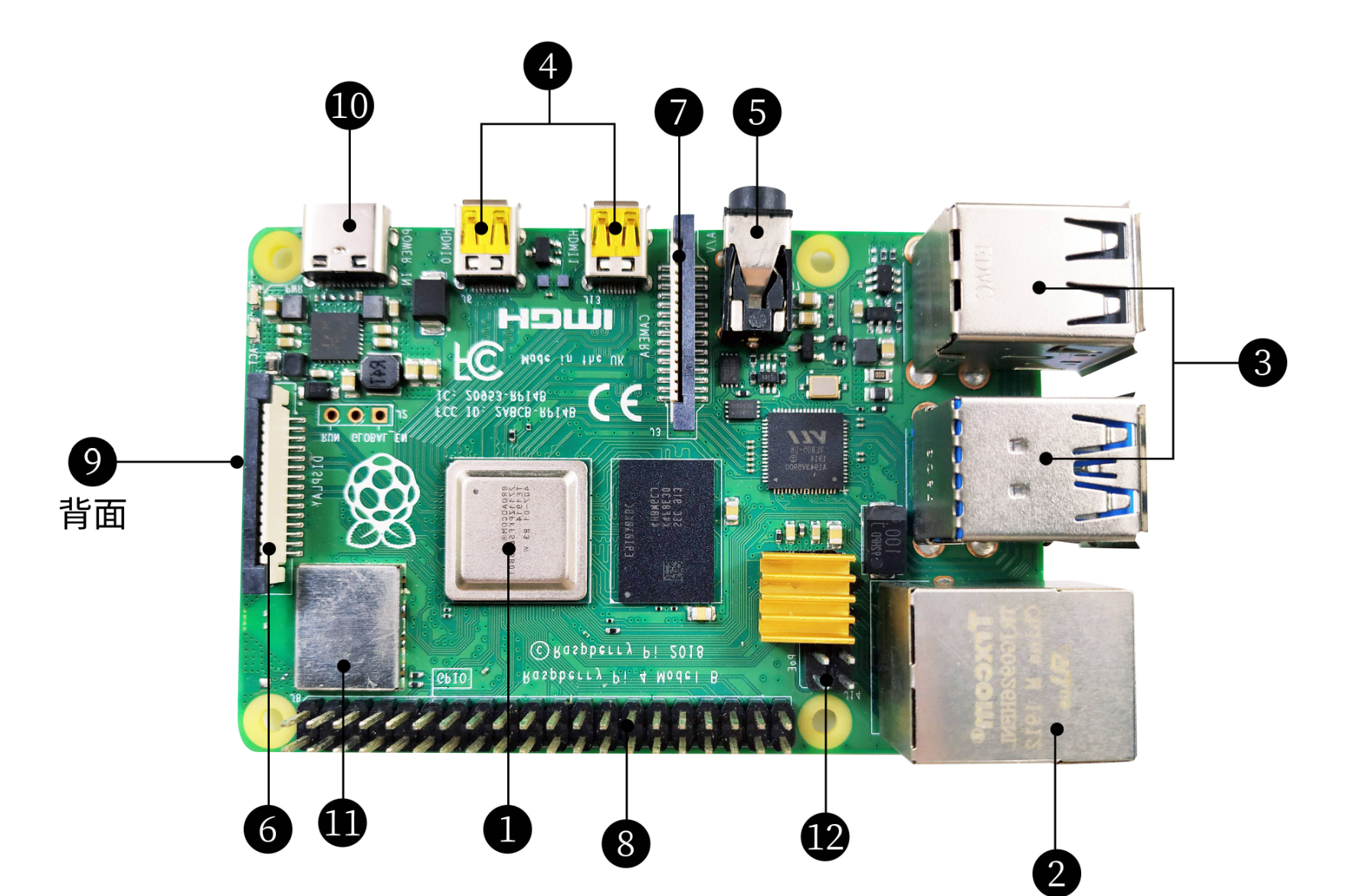 b.Functions: With video, audio output and other basic functions, you can edit Office documents, browse the web, play games and so on.
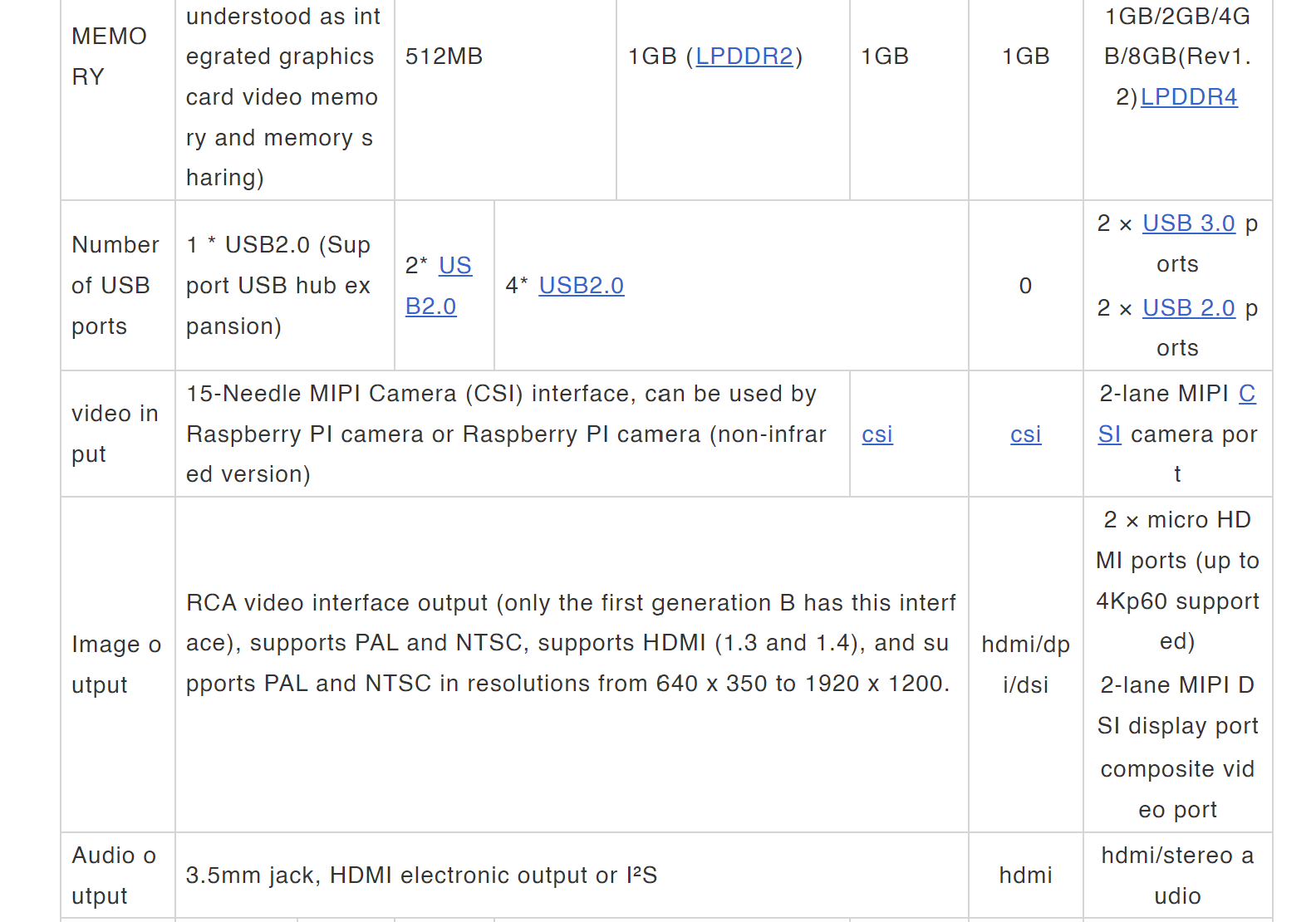
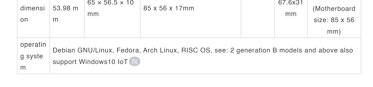
c.Memory and storage: Initially using SD/MicroSD cards as memory and hard disk, later models offer different size memory configurations such as 256MB, 512MB, 1GB, etc.
b.Functions: With video, audio output and other basic functions, you can edit Office documents, browse the web, play games and so on.
c.Memory and storage: Initially using SD/MicroSD cards as memory and hard disk, later models offer different size memory configurations such as 256MB, 512MB, 1GB, etc.
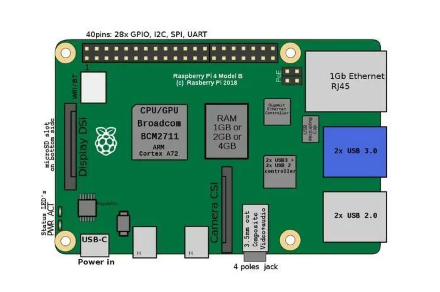 d.Widely used: widely used in industrial scenarios, Internet of things , smart agriculture, artificial intelligence, new energy and other fields.
e.Educational purpose: The Raspberry PI Foundation hopes this computer will promote computer science education and make computers fun in different countries.
d.Widely used: widely used in industrial scenarios, Internet of things , smart agriculture, artificial intelligence, new energy and other fields.
e.Educational purpose: The Raspberry PI Foundation hopes this computer will promote computer science education and make computers fun in different countries.
 f.Programming language support: Python, Scratch, C++, JavaScript and other programming languages.
g.Media Center: By connecting the TV or monitor, using the corresponding operating system and media playback software, it can be transformed into a multimedia center.
h.Iot applications: Suitable for use in iot applications, connecting to various sensors and devices, collecting data and analyzing it.
i.Educational and research experiments: used in schools and universities to teach computer science, electrical engineering and other courses, or used in research projects.
f.Programming language support: Python, Scratch, C++, JavaScript and other programming languages.
g.Media Center: By connecting the TV or monitor, using the corresponding operating system and media playback software, it can be transformed into a multimedia center.
h.Iot applications: Suitable for use in iot applications, connecting to various sensors and devices, collecting data and analyzing it.
i.Educational and research experiments: used in schools and universities to teach computer science, electrical engineering and other courses, or used in research projects.

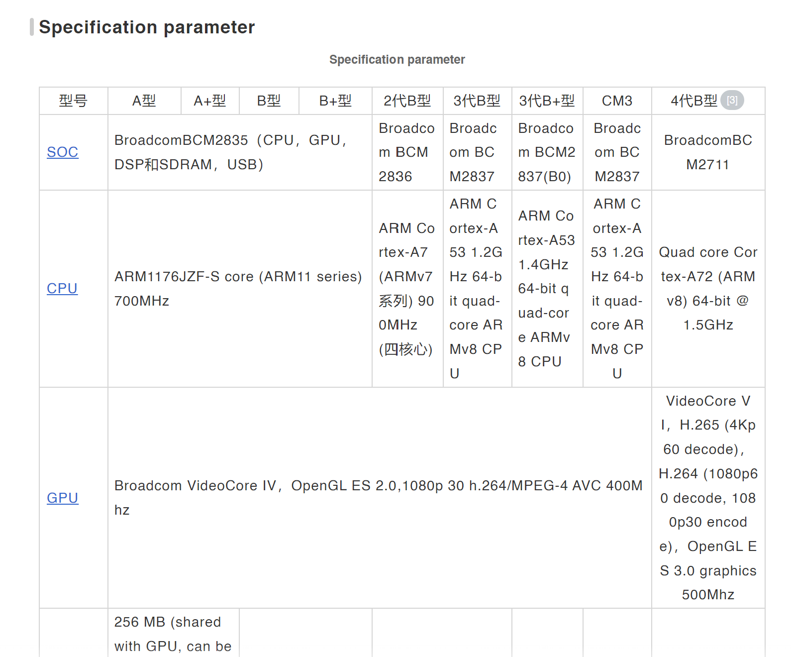
 Raspberry PI models include Model A, Model A+, Model B, Model B+, Model 2, Model 3, Model 3, Model 3, Compute Module, and Model 4, with performance and features varying by model.


void setup() {
    // 初始化代码
  }

void loop() {
    // 持续运行的代码
  }
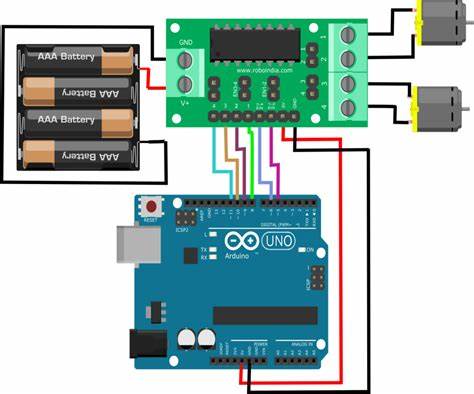
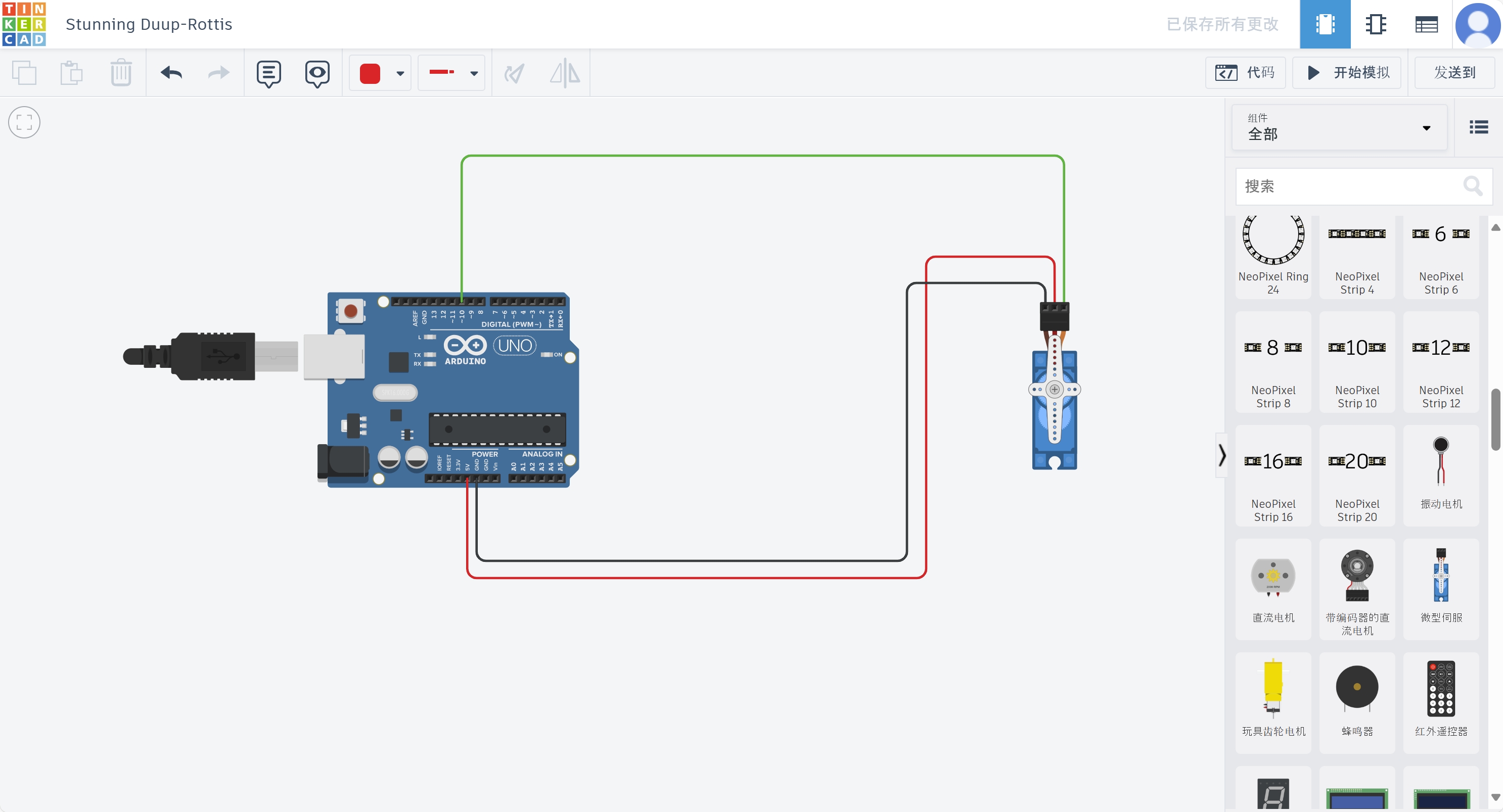
This experiment utilizes an Arduino board to manipulate a servo motor. The motor will sweep back and forth, pausing for a second at each of the positions - 0, 40, and 80 degrees.
1. Arduino Development Board
2. Servo Motor
3. Jumper Wires
Before connecting the servo, it is essential to comprehend the control mechanism:
Servo motors are essentially low-cost servo motor systems and work by receiving PWM pulse modulation signaling through their internal circuitry. This signal controls the movement of the inbuilt motor, which in turn engages a series of reduction gears, transferring torque to the output shaft. A potentiometer connected to the output shaft gives feedback on position, enabling precise motor positioning.
The SG90 servo has three wires: the power wire (red), ground wire (black or brown), and signal wire (yellow, orange, or white).
After connections are made, upload the following code to the Arduino board:

        #include <Servo.h>

        #define PIN_SERVO 10
        Servo myservo;

        void setup()
        {
          myservo.attach(PIN_SERVO);
        }

        void loop()
        {
          myservo.write(0);
          delay(1000);
          myservo.write(40);
          delay(1000);
          myservo.write(80);
          delay(1000);
          myservo.write(40);
          delay(1000);
          myservo.write(0);
          delay(1000);
        }
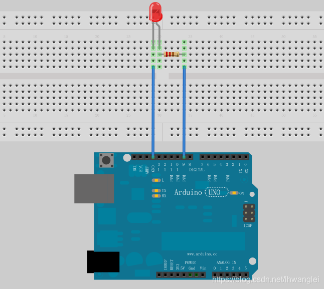
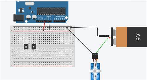
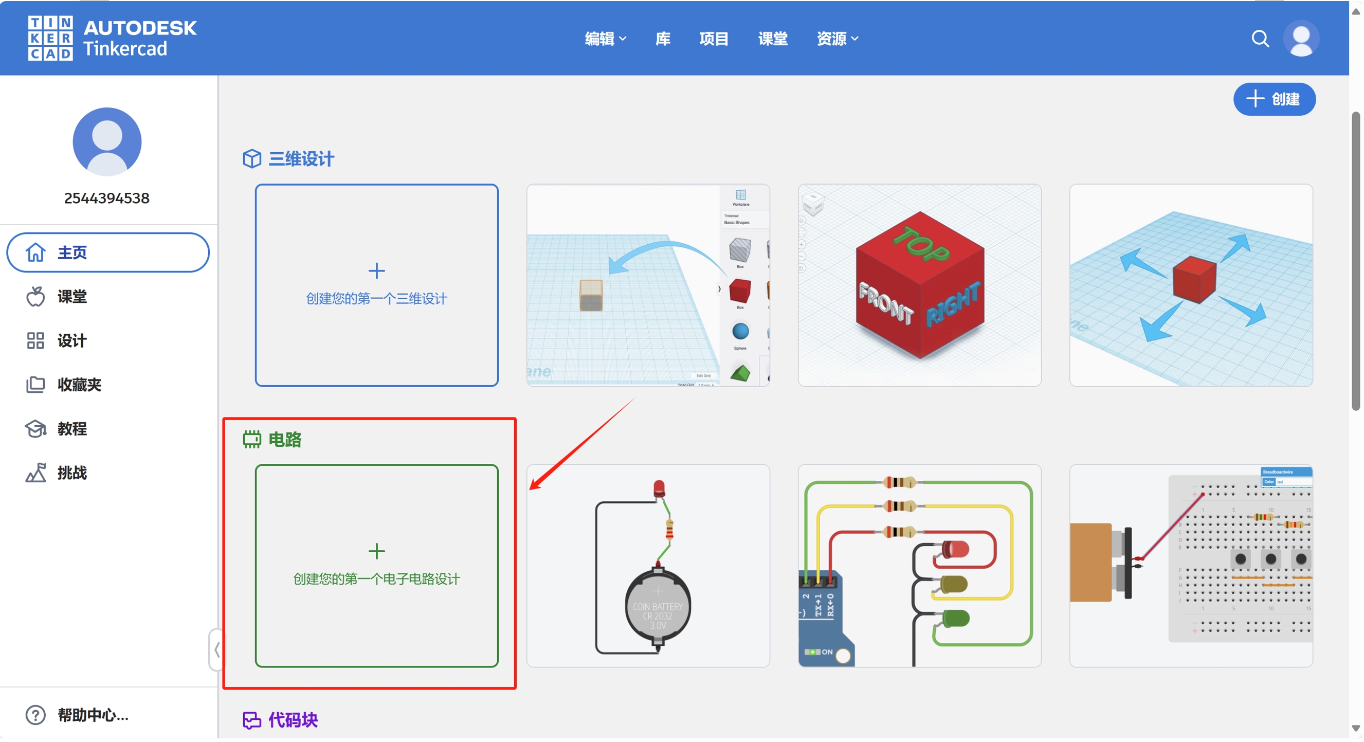
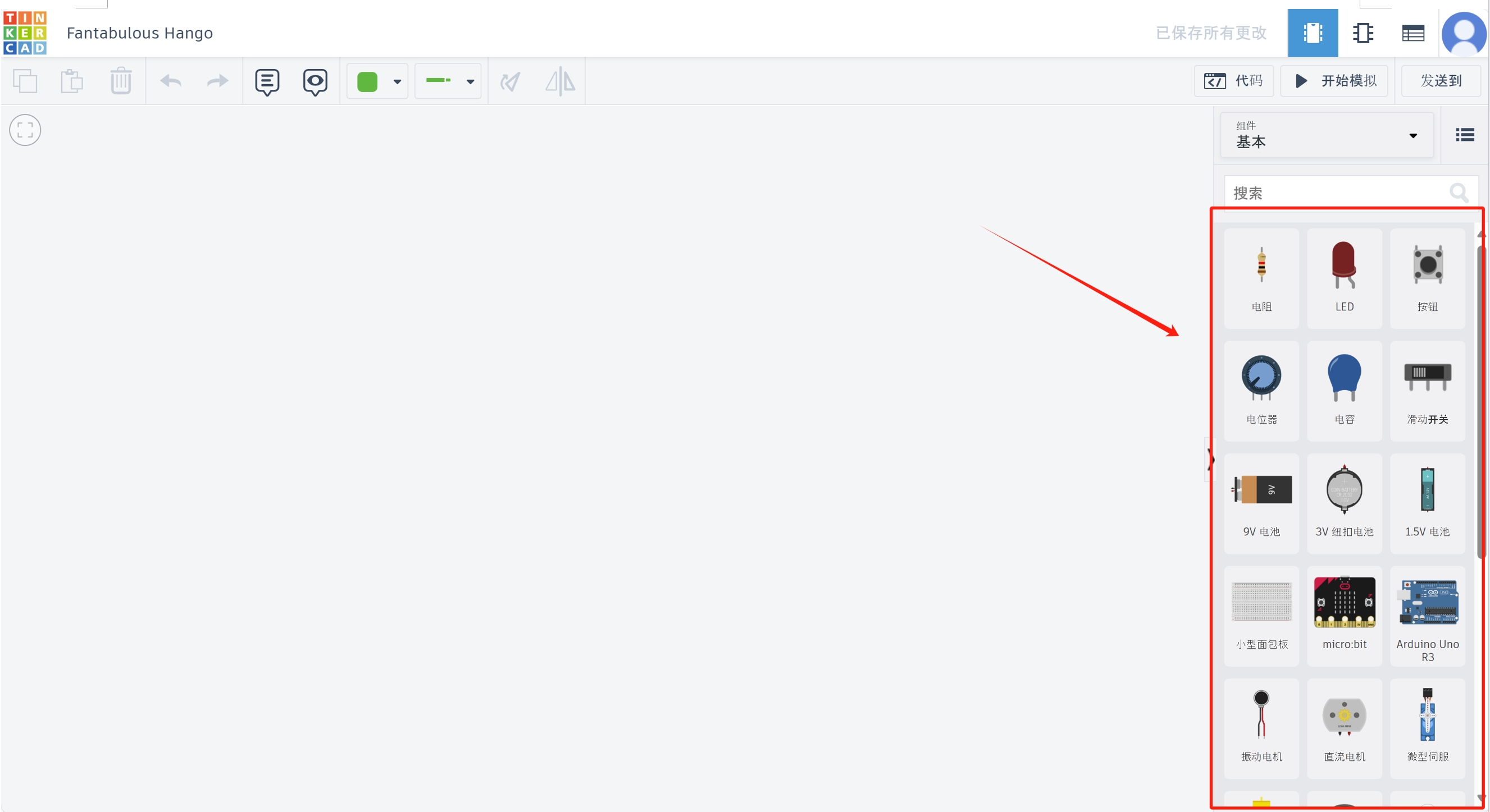
Creating circuit diagrams using Tinkercad can very visually show the design of the entire project. This process can help understand how each component is connected and provide a visual guide for creating a physical prototype. You can be in the here to check the detailed steps.

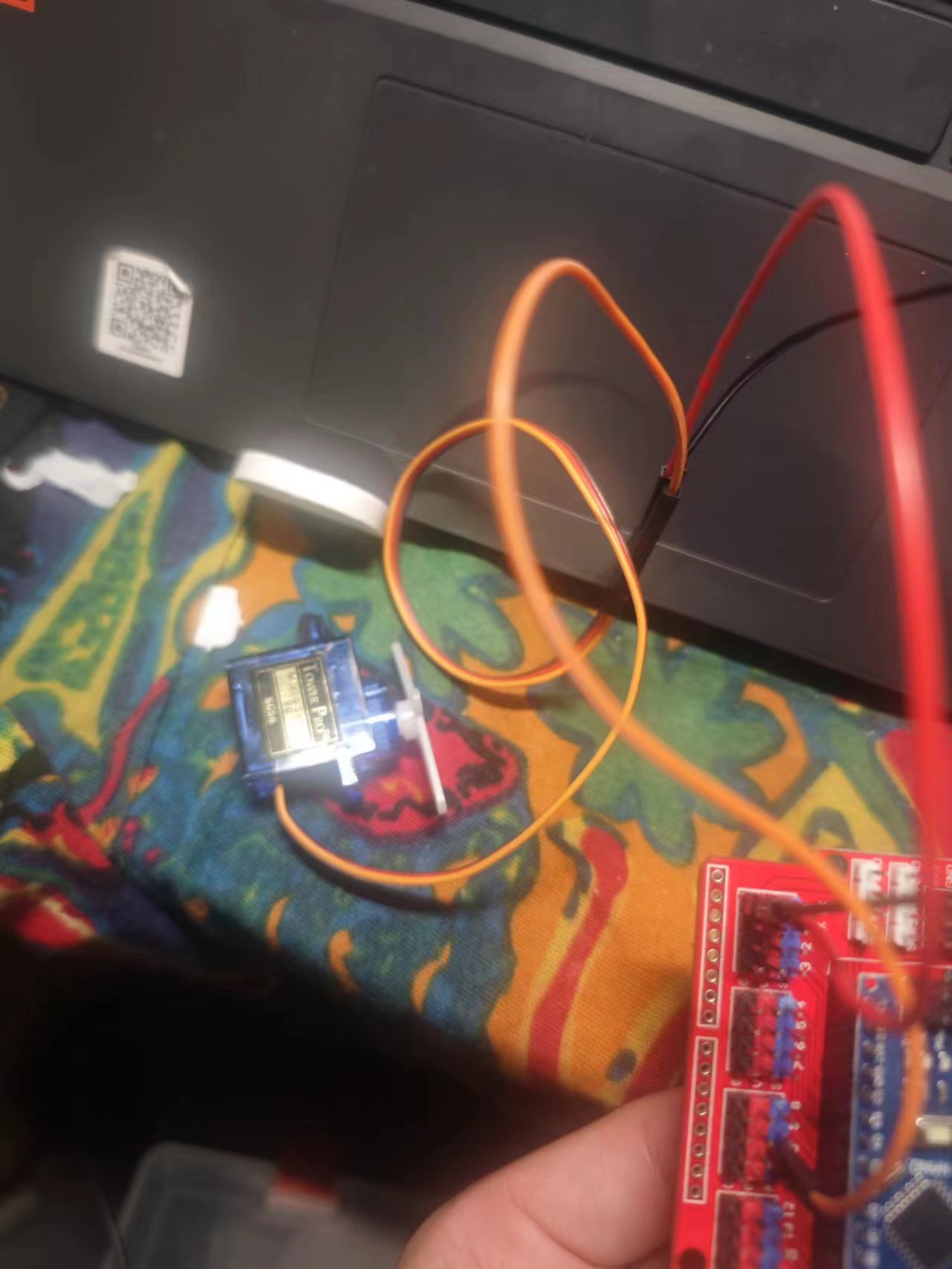
Once the code is uploaded to the Arduino board, the servo motor should actuate accordingly, pausing at the specified positions of 0, 40, and 80 degrees for one second each.
This experiment demonstrates precise servo motor control using an Arduino. Simple code instructions enable the manipulation of motor movements between pre-specified positions. This is an insightful experiment for understanding the principles of servo motors and programming them for precision control.
This code belongs to an example program that uses Arduino to control the NeoPixel LED light strip. Arduino is an easy to use and open source electronic prototyping platform, while NeoPixel is a series of LED products produced by Adafruit Industries that have built-in WS2811/WS2812 driver chips that individually control the color and brightness of each LED.
water light effect: the unlit lights are lit one by one, and then gradually extinguished from the beginning end, you can cycle, of course, you can also have other effects, you can set yourself.
1. Arduino UNO
2. Jumper
3. WS2812B RGB LED ring or NeoPixel LED light strip
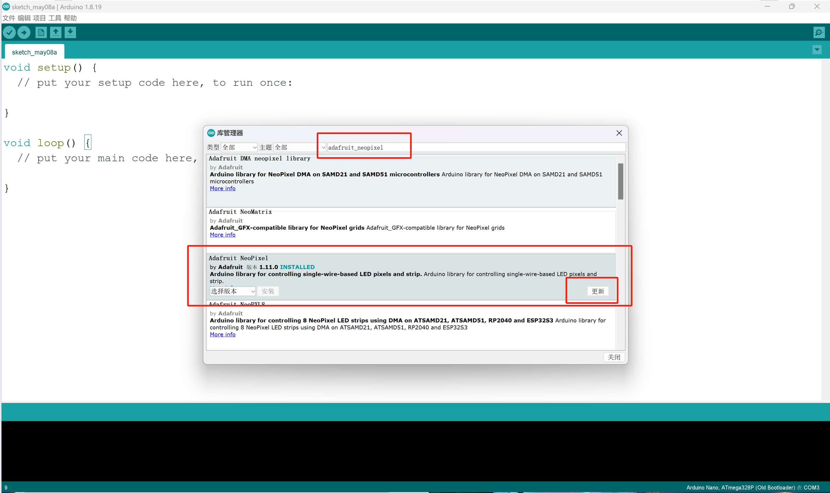
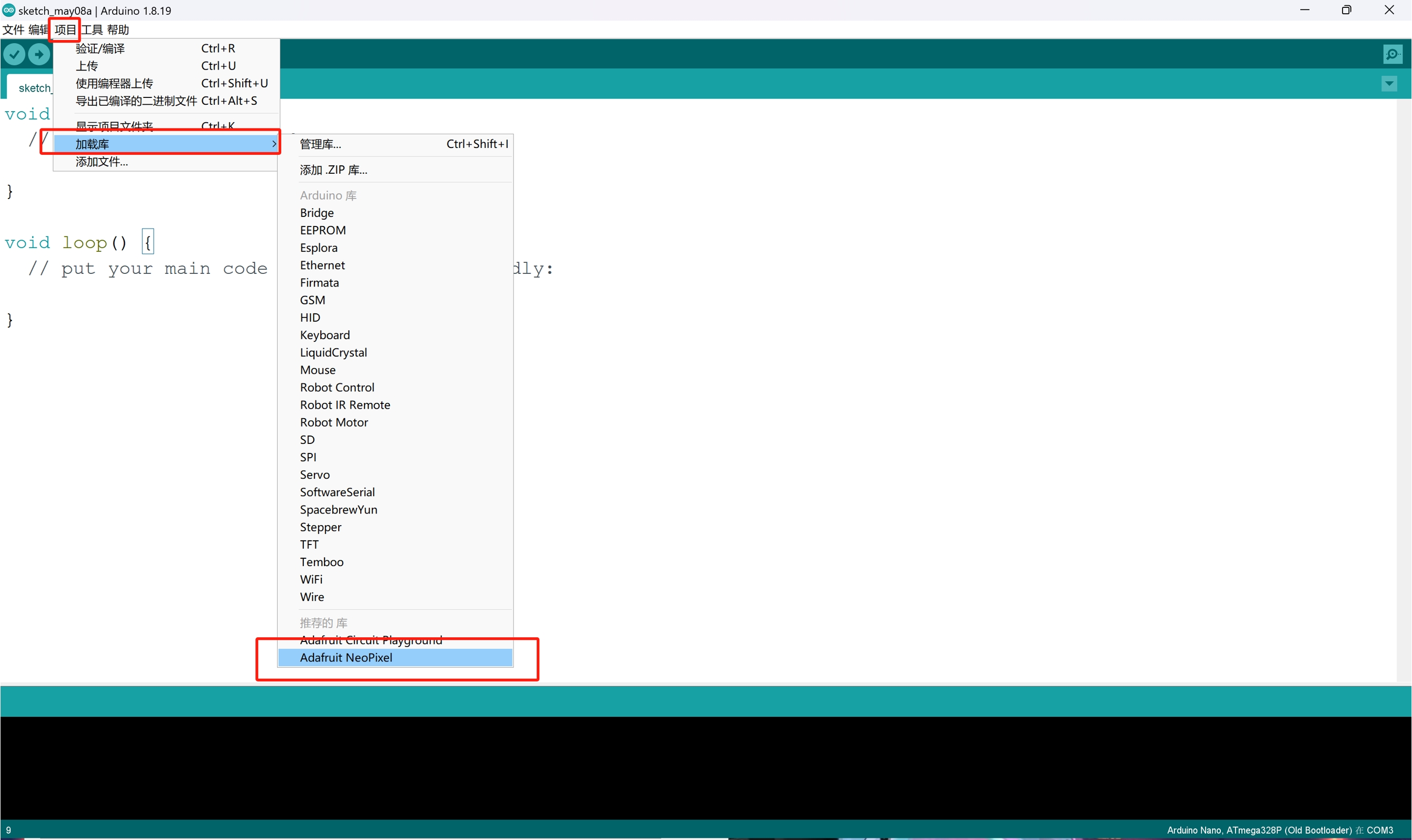
Before you start programming, you need to install the Adafruit_NeoPixel library. It can be found and installed in "Library Manager" in the Arduino IDE.
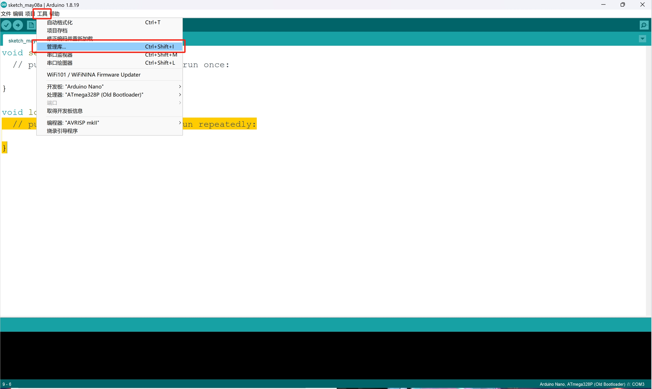
In the Arduino IDE, click on "Tools" -> "Manage Library..." ", then type "Adafruit NeoPixel" in the search box, find it and click "Install".
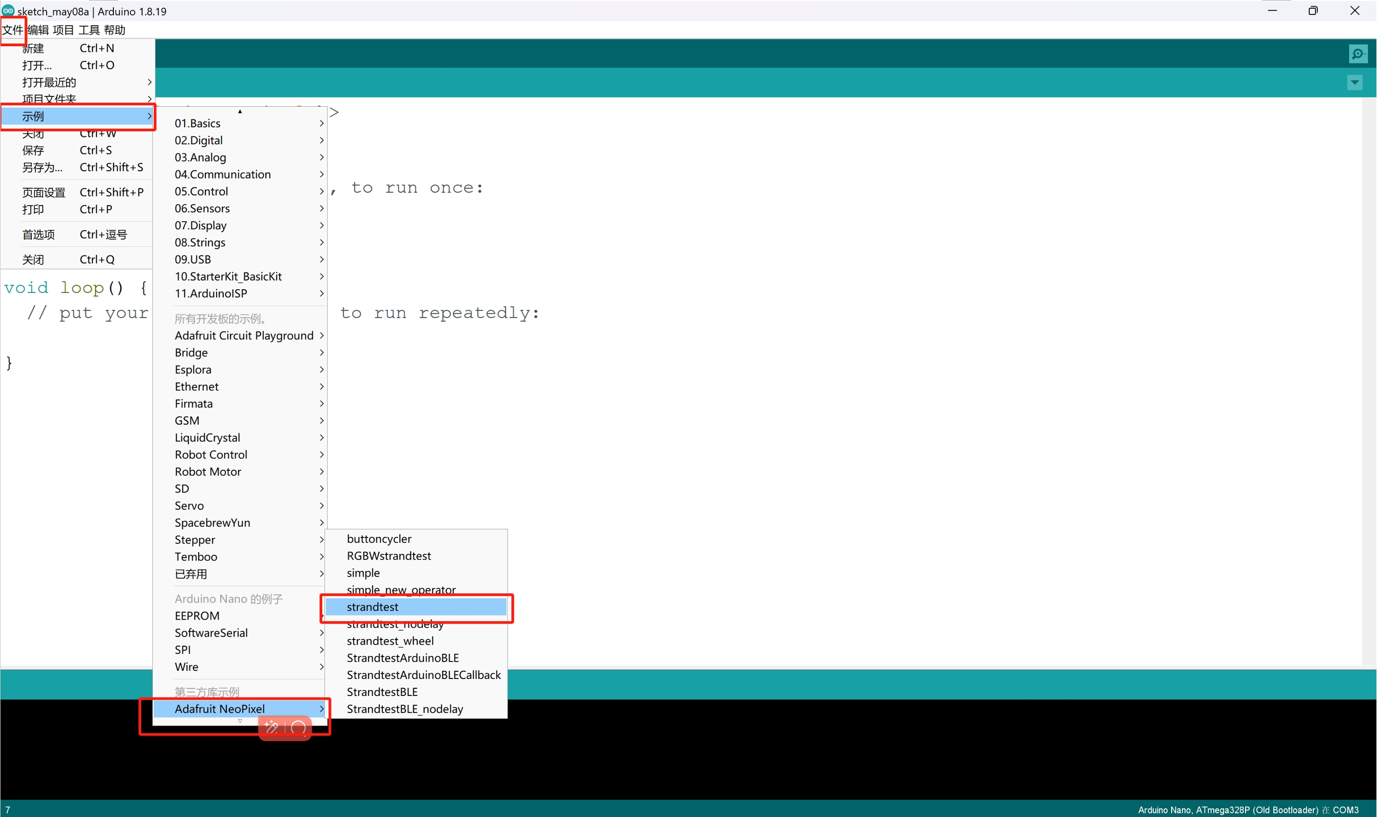
After installing the library file, select the sample you want to open in "File" -> "Example" -> "Adafruit NeoPixel".
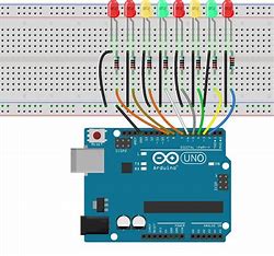
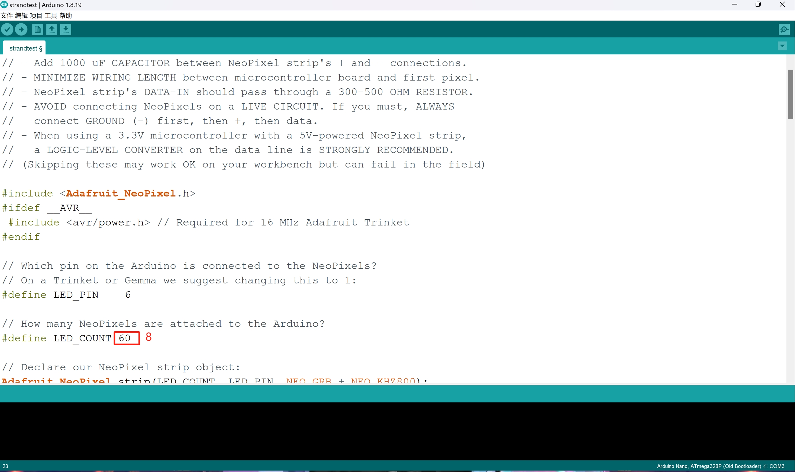
An LED strip with eight beads is used here, so the number of leds in the code and possible pin numbers need to be modified according to the actual device.
Arduino IDE
          // A basic everyday NeoPixel strip test program.

          // NEOPIXEL BEST PRACTICES for most reliable operation:
          // - Add 1000 uF CAPACITOR between NeoPixel strip's + and - connections.
          // - MINIMIZE WIRING LENGTH between microcontroller board and first pixel.
          // - NeoPixel strip's DATA-IN should pass through a 300-500 OHM RESISTOR.
          // - AVOID connecting NeoPixels on a LIVE CIRCUIT. If you must, ALWAYS
          //   connect GROUND (-) first, then +, then data.
          // - When using a 3.3V microcontroller with a 5V-powered NeoPixel strip,
          //   a LOGIC-LEVEL CONVERTER on the data line is STRONGLY RECOMMENDED.
          // (Skipping these may work OK on your workbench but can fail in the field)

          #include <Adafruit_NeoPixel.h>
          #ifdef __AVR__
           #include <avr/power.h> // Required for 16 MHz Adafruit Trinket
          #endif

          // Which pin on the Arduino is connected to the NeoPixels?
          // On a Trinket or Gemma we suggest changing this to 1:
          #define LED_PIN    6

          // How many NeoPixels are attached to the Arduino?
          #define LED_COUNT 60

          // Declare our NeoPixel strip object:
          Adafruit_NeoPixel strip(LED_COUNT, LED_PIN, NEO_GRB + NEO_KHZ800);
          // Argument 1 = Number of pixels in NeoPixel strip
          // Argument 2 = Arduino pin number (most are valid)
          // Argument 3 = Pixel type flags, add together as needed:
          //   NEO_KHZ800  800 KHz bitstream (most NeoPixel products w/WS2812 LEDs)
          //   NEO_KHZ400  400 KHz (classic 'v1' (not v2) FLORA pixels, WS2811 drivers)
          //   NEO_GRB     Pixels are wired for GRB bitstream (most NeoPixel products)
          //   NEO_RGB     Pixels are wired for RGB bitstream (v1 FLORA pixels, not v2)
          //   NEO_RGBW    Pixels are wired for RGBW bitstream (NeoPixel RGBW products)

          // setup() function -- runs once at startup --------------------------------

          void setup() {
            // These lines are specifically to support the Adafruit Trinket 5V 16 MHz.
            // Any other board, you can remove this part (but no harm leaving it):
            #if defined(__AVR_ATtiny85__) && (F_CPU == 16000000)
              clock_prescale_set(clock_div_1);
            #endif
            // END of Trinket-specific code.

            strip.begin();           // INITIALIZE NeoPixel strip object (REQUIRED)
            strip.show();            // Turn OFF all pixels ASAP
            strip.setBrightness(50); // Set BRIGHTNESS to about 1/5 (max = 255)
          }

          // loop() function -- runs repeatedly as long as board is on ---------------

          void loop() {
            // Fill along the length of the strip in various colors...
            colorWipe(strip.Color(255,   0,   0), 50); // Red
            colorWipe(strip.Color(  0, 255,   0), 50); // Green
            colorWipe(strip.Color(  0,   0, 255), 50); // Blue

            // Do a theater marquee effect in various colors...
            theaterChase(strip.Color(127, 127, 127), 50); // White, half brightness
            theaterChase(strip.Color(127,   0,   0), 50); // Red, half brightness
            theaterChase(strip.Color(  0,   0, 127), 50); // Blue, half brightness

            rainbow(10);             // Flowing rainbow cycle along the whole strip
            theaterChaseRainbow(50); // Rainbow-enhanced theaterChase variant
          }

          // Some functions of our own for creating animated effects -----------------

          // Fill strip pixels one after another with a color. Strip is NOT cleared
          // first; anything there will be covered pixel by pixel. Pass in color
          // (as a single 'packed' 32-bit value, which you can get by calling
          // strip.Color(red, green, blue) as shown in the loop() function above),
          // and a delay time (in milliseconds) between pixels.
          void colorWipe(uint32_t color, int wait) {
            for(int i=0; i RGB
                  strip.setPixelColor(c, color); // Set pixel 'c' to value 'color'
                }
                strip.show();                // Update strip with new contents
                delay(wait);                 // Pause for a moment
                firstPixelHue += 65536 / 90; // One cycle of color wheel over 90 frames
              }
            }
          }
Adafruit_NeoPixel library: This library provides an easy to use interface to control the LED lamp beads of the WS2811/WS2812 model.
Preprocessor instruction:
#include < Adafruit_NeoPixel.h>
This is the C++ preprocessor instruction used to include the
Adafruit NeoPixel library so that the functionality provided by the library can be used in your
program.
Pin definition:
#define LED_PIN 6
Define the pin number on the Arduino board to connect NeoPixel.
In this code, the data signal line is connected to digital pin 6.
LED number definition:
#define LED_COUNT 8
Defines the number of NeoPixel lamp beads attached to the
Arduino board.
NeoPixel object initialization:
Adafruit_NeoPixel strip(LED_COUNT, LED_PIN, NEO_GRB
+ NEO_KHZ800);
This line of code creates a new Adafruit_NeoPixel object, which
represents the entire LED strip you control.
setup function (setup) :
void setup()
Is the part of the code that runs only once when the Arduino
board is started. Initializes the NeoPixel object and sets the brightness of the LED.
Main loop function (loop) :
void loop()
Includes various animation effects that control LED strips, such as
"colorWipe" and "theaterChase." These functions are included in the main program loop and
are called through the loop to create the animation effect.
Custom function:
void colorWipe(uint32_t color, int wait)
Etc., is a custom function written to create animation effects. For
example, the colorWipe function changes the color of the LED lights one by
one, and theaterChase creates a running horselight effect.
Creating circuit diagrams using Tinkercad can very visually show the design of the entire project. This process can help understand how each component is connected and provide a visual guide for creating a physical prototype. You can be in the here to check the detailed steps.
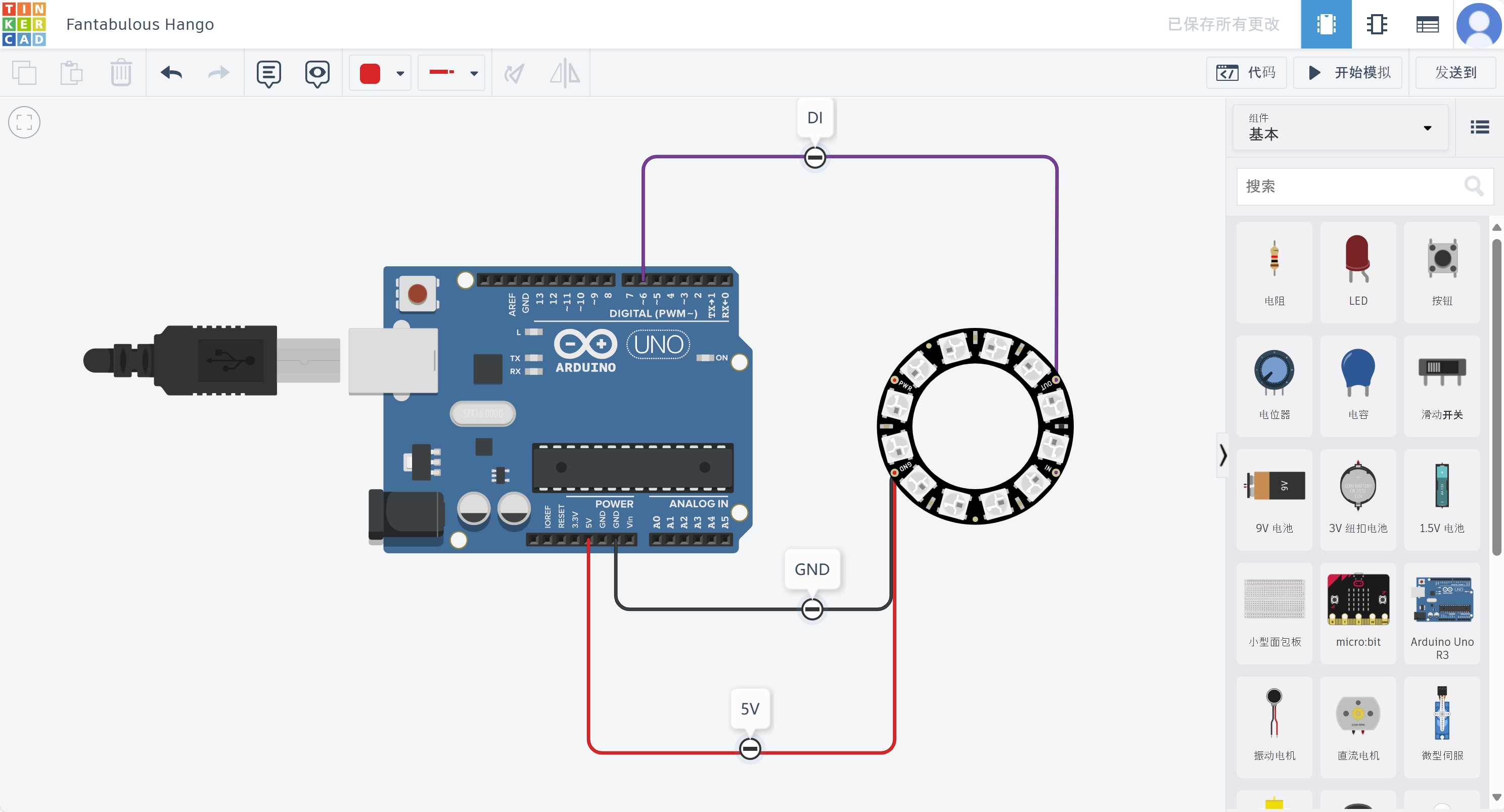
Once the code has been uploaded to the Arduino board, the LED strip should display the set water light effect. This process may require some tuning, but as you make adjustments in the code, you will see different lighting effects.

STEP-2 : Follow the wiring diagram to create the electrical circuit.
STEP-3 : Make a book cover.
STEP-4 : Set up and Light up.
STEP-2 :
DESIGN BASIS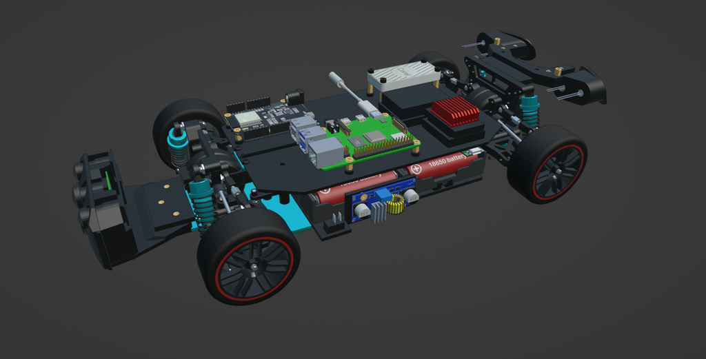
STEP-3 :
Design Recommendations - BEFORE STARTING 3D PRINTING Efficient 3D Design: Use 3D design software like SolidWorks, Fusion 360, Tinkercad, or Blender to create your model. Print Orientation: Plan the orientation of the part on the 3D printer to minimize the need for supports. Printing Material: Choose a suitable material for your application. Wall Thickness and Infill: Adjust the wall thickness and infill of your design according to your needs. Easy Assembly: Design parts that are easy to assemble without the need for additional tools. Consider Tolerances: Take into account tolerances to ensure that the printed parts fit together properly. Modular Structure: Divide the structure into smaller modules that can be printed separately and then assembled. Iterative Testing: Prototype and test with 3D-printed parts before printing the complete structure. Documentation: Document your design in detail. Provide clear assembly instructions, a parts list, and any additional information that might be useful for others looking to build the same robot. Consider Functionality: Ensure that the structure can accommodate all necessary components. Strategic Reinforcements: If needed, you can add reinforcements in critical areas of the structure to increase strength and durability. Optimize for Weight: If mobility is a significant factor, look for ways to optimize the weight of the structure without compromising strength. Respect Copyrights: If you are using pre-existing designs or third-party components, make sure to respect copyrights and relevant licenses.STEP-4 :
3D PRINTING: Grille-Front Bumper, Cameras Support & Sensor Support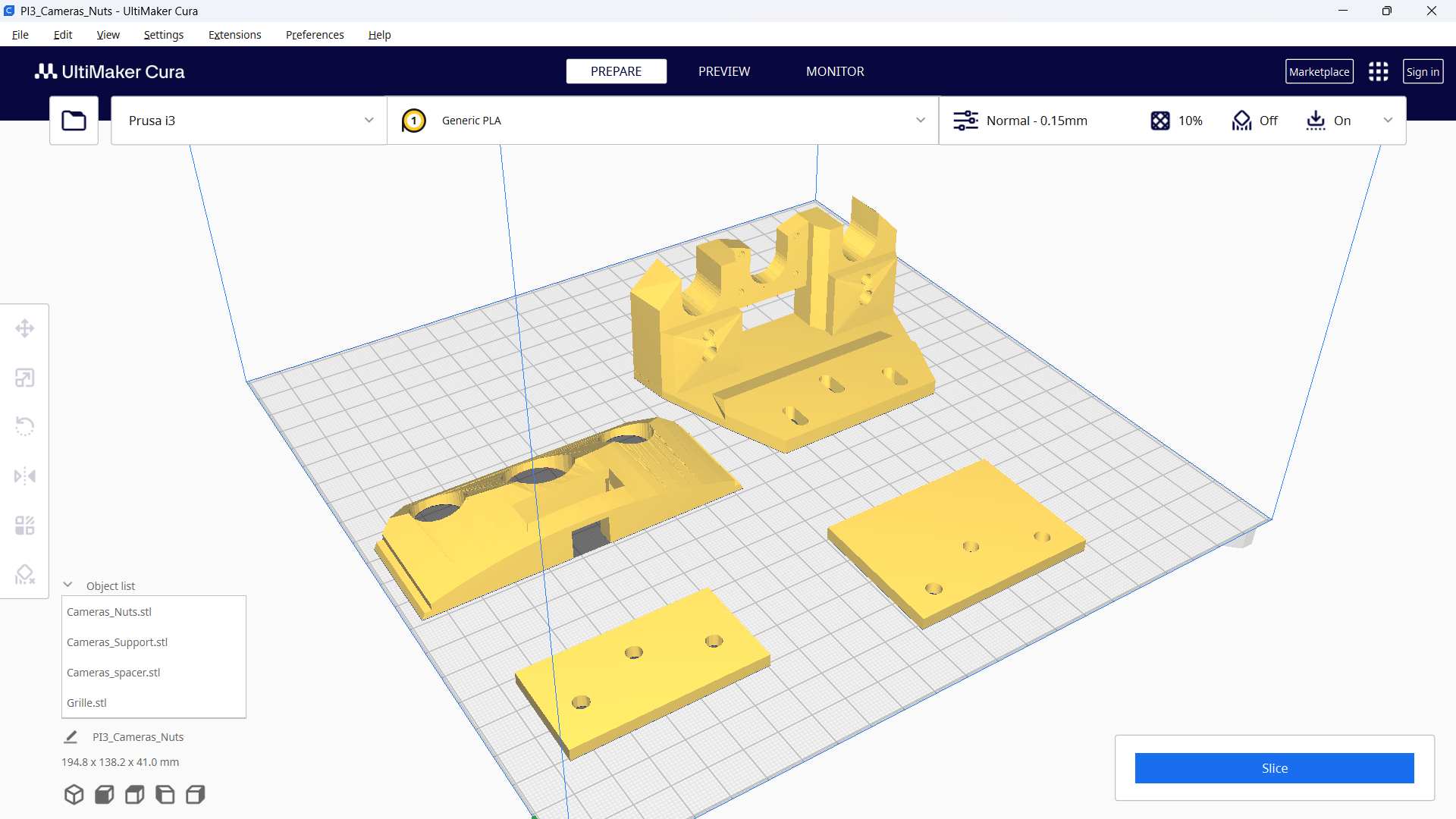
STEP-5 :
3D PRINTING: Battery Holder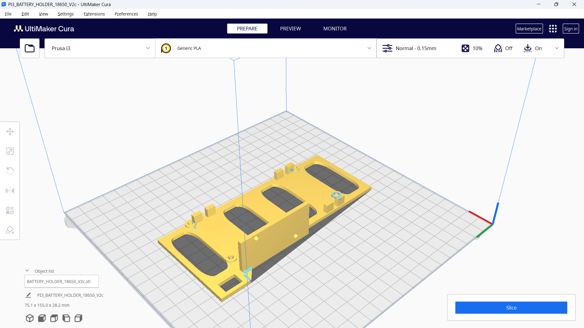
STEP-6 :
3D PRINTING: Electronic Components BaseSTEP-7 :
3D PRINTING: Rear LightsSTEP8 :
3D PRINTING: Car Treadmill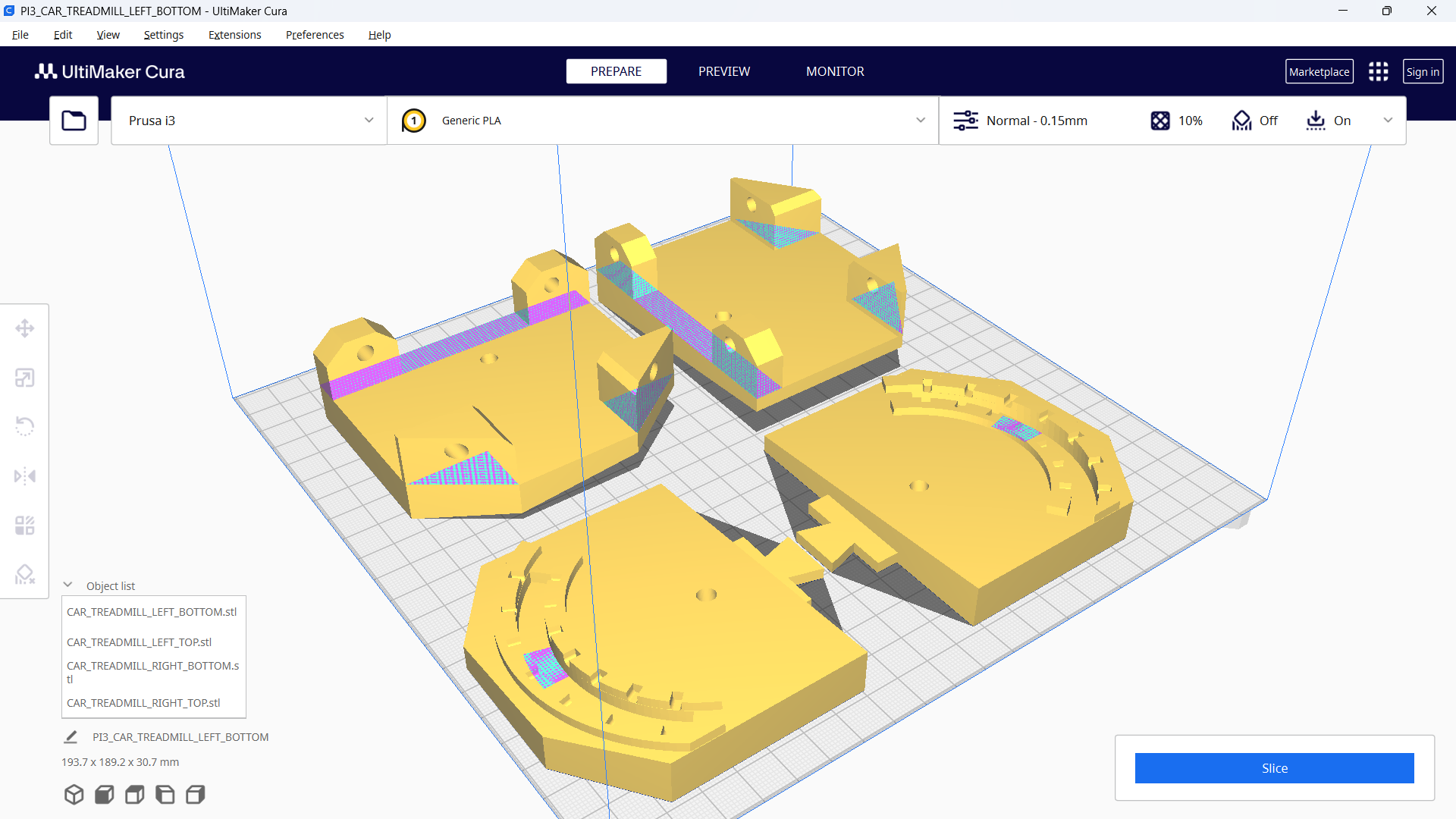
STEP-9 :
3D PRINTING: Post ProcessingSTEP-10 :
POST PROCESSING
STEP-11:
HEAT SET INSERTSSTEP-12 :
PLACING HEXAGONAL SPACERSSTEP-13 :
COMPONENT DESCRIPTION: Raspberry Pi 4
STEP-14 :
COMPONENT DESCRIPTION: Wemos D1 R32
STEP-15:
COMPONENT DESCRIPTION: Synchronized Dual Lens Stereo USB CameraSTEP-16 :
COMPONENT DESCRIPTION: CablesSTEP-17 :
COMPONENT DESCRIPTION: Raspberry Camera & Fisheye Lens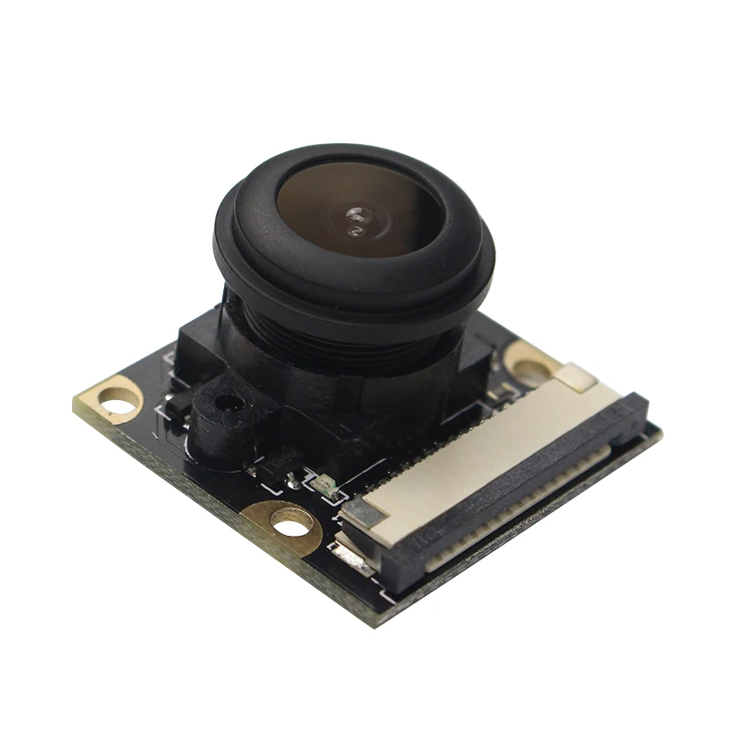
STEP-18 :
COMPONENT DESCRIPTION: Motor & Controller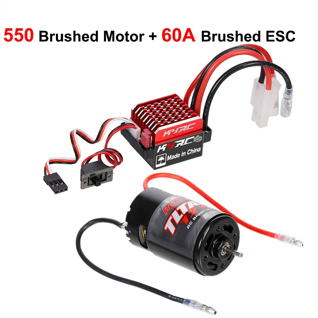
STEP-19 :
COMPONENT DESCRIPTION: Google Coral USB AcceleratorSTEP-20 :
PLACING DECALS & REINFORCING THE CAR BODYSTEP-21 :
CUTTING HOLES: Grille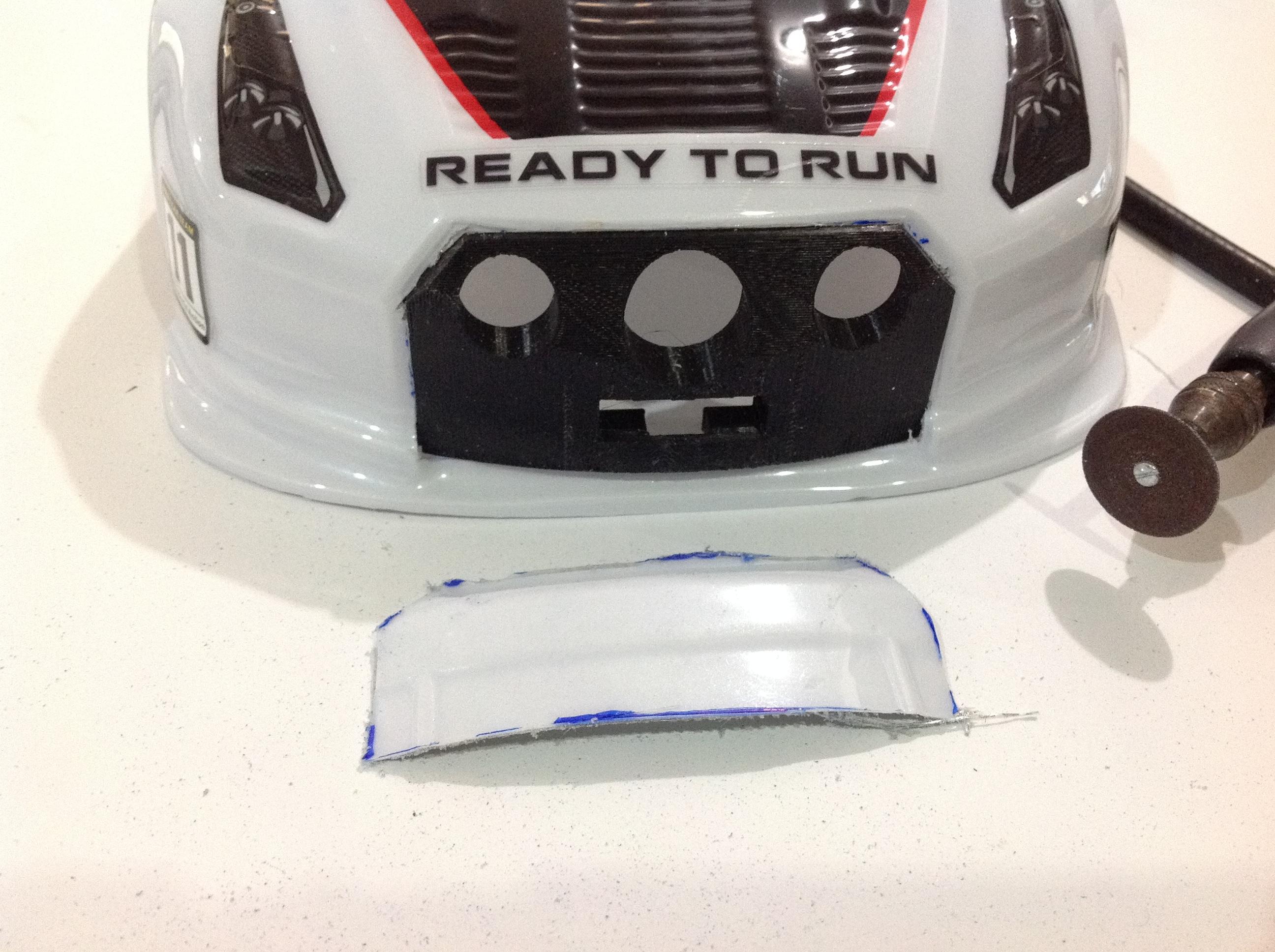
STEP-22 :
CUTTING HOLES: Rear LightsSTEP-23 :
OPTION A: Mounting the SHARP Distance Sensor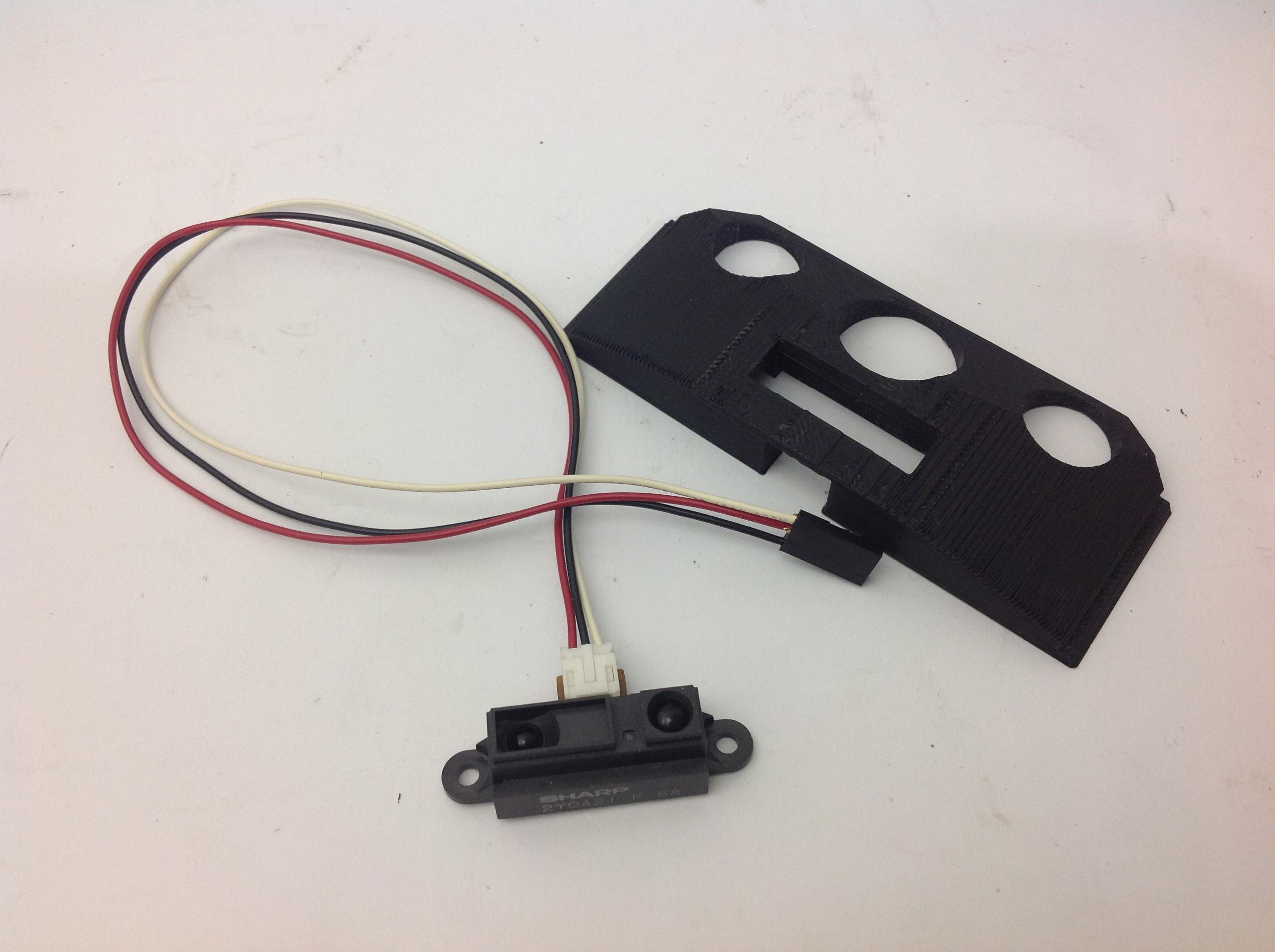 STEP-24 : OPTION B: Mounting the Laser Distance Sensor
STEP-25 :
Installing the Grille (OPTION A) and Cameras Together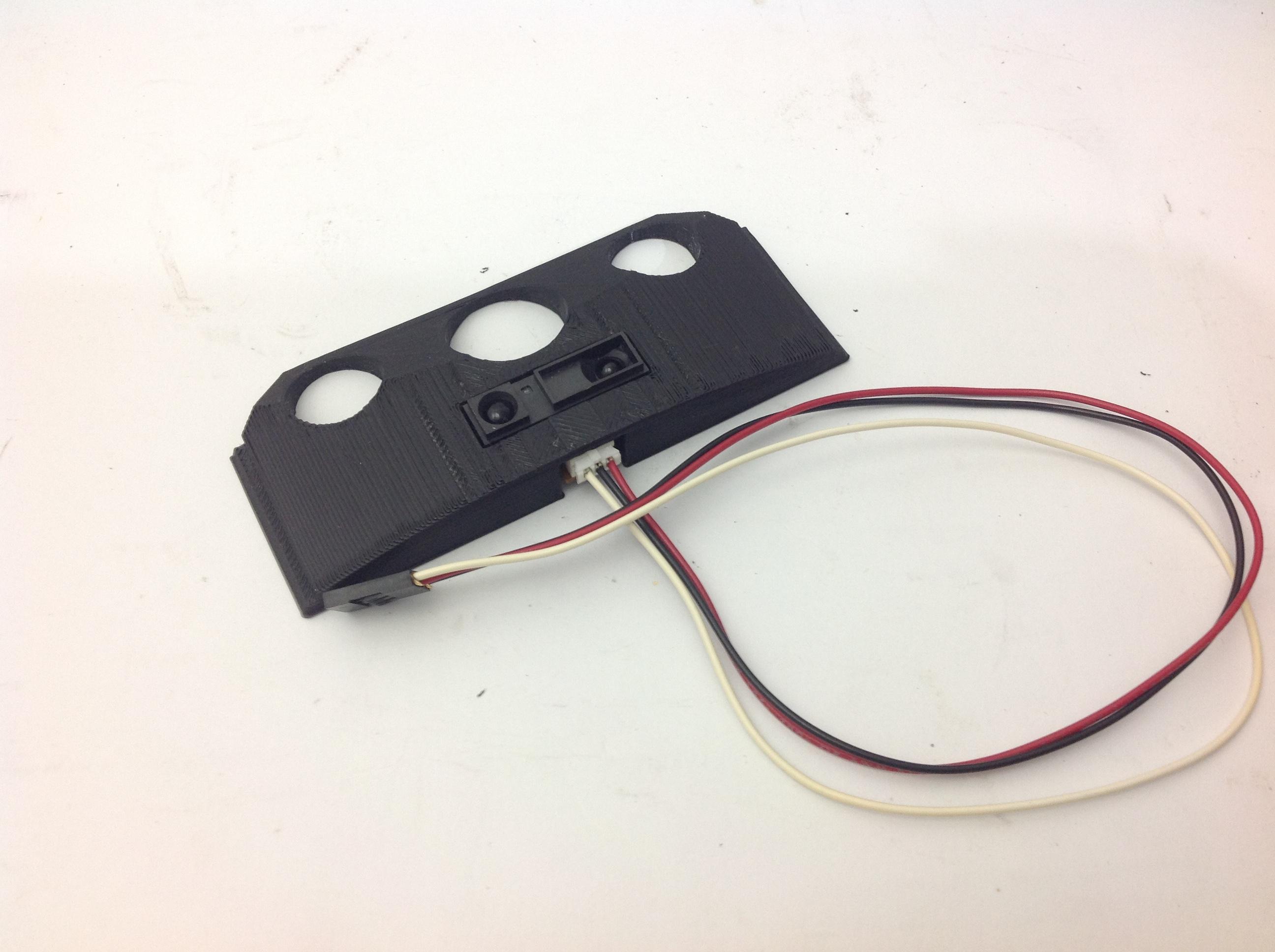
STEP-26 :
Before Starting to Assemble: ELECTRICAL SYSTEMSTEP-27 :
ELECTRICAL SYSTEM: Switch & StepDown ConverterSTEP-28 :
ELECTRICAL SYSTEM: Battery WiringSTEP-29 :
ELECTRICAL SYSTEM: Regulator & Switch WiringSTEP-30 :
ELECTRICAL SYSTEM: Voltage AdjustingSTEP-31:
ELECTRICAL SYSTEM: Battery Wiring for MotorSTEP-32 :
ELECTRICAL SYSTEM: Gluing the Battery HolderSTEP-33 :
ELECTRICAL SYSTEM: SOLDERING USB TYPE C CONNECTORSTEP-34 :
HSP 94123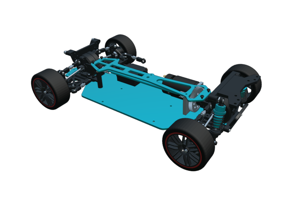
STEP-35 :
HSP 94123: FRONT SUSPENCIONSTEP-36 :
FRONT DIFERENTIALSTEP-37 :
Front Suspension AssemblySTEP-38 :
TRANSMISIONSTEP-39 :
Installing the Grille and Cameras on the CarSTEP-40 :
Rear Suspension AssemblySTEP-41 :
Rear Suspension MountingSTEP-42 :
Mounting the ELECTRICAL SYSTEM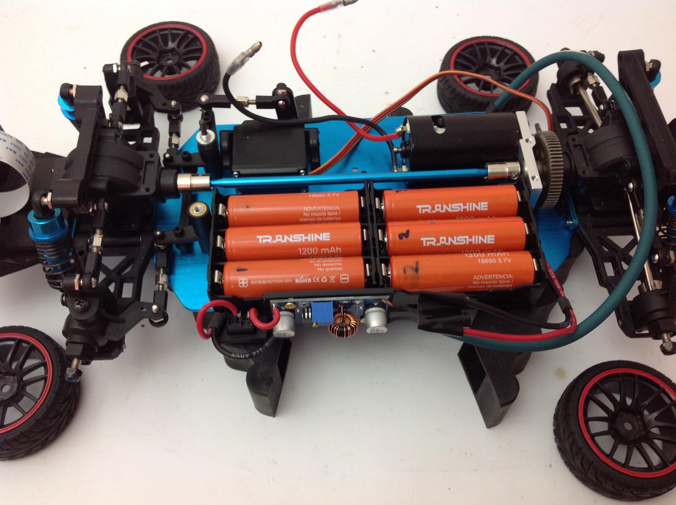
STEP-43 :
Mounting the Electronic Components BaseSTEP-44 :
REAR LIGHTSSTEP-45:
REAR LIGHTS PRO (UPDATED VERSION: PCB & 3D PRINTER FILES)
STEP-46 :
GEARBOX ANALYSISSTEP-47 :
Remote Control: Code Matching Steps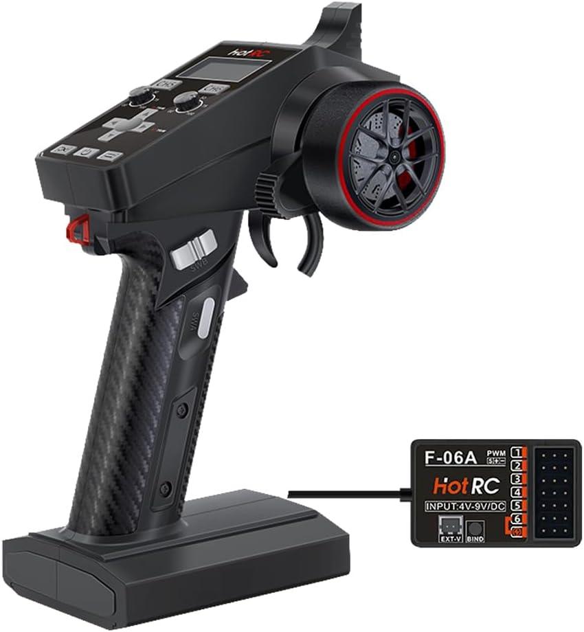
STEP-48 :
TREADMILLSTEP-49 :
TREADMILL: PVC CuttingSTEP-50 :
TREADMILL: PVC PaintingSTEP-51 :
TREADMILL: Roller AssemblySTEP-52 :
TREADMILL: Roller Front Support AssemblySTEP-53 :
TREADMILL: Roller Rear Support AssemblySTEP-54 :
TREADMILL: Putting It All TogetherSTEP-55 :
TEST REAR LIGHTS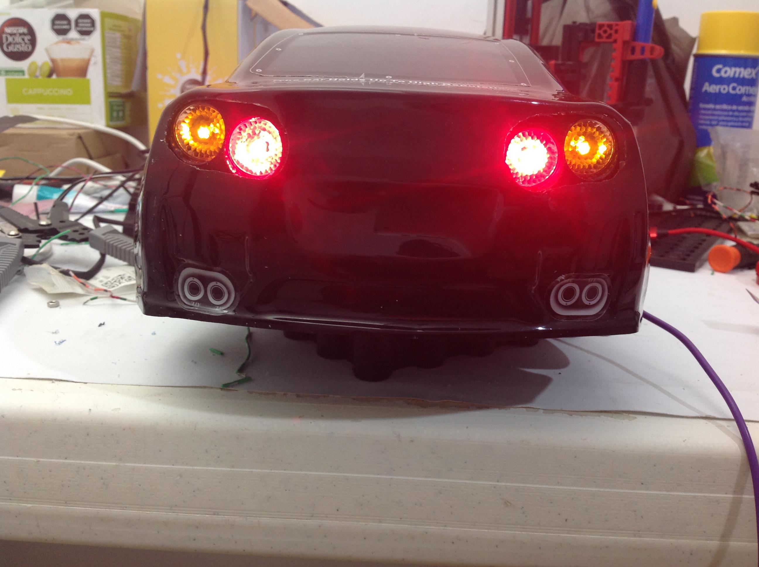
STEP-56 :
BLENDER