CAD design
First, open fusion360
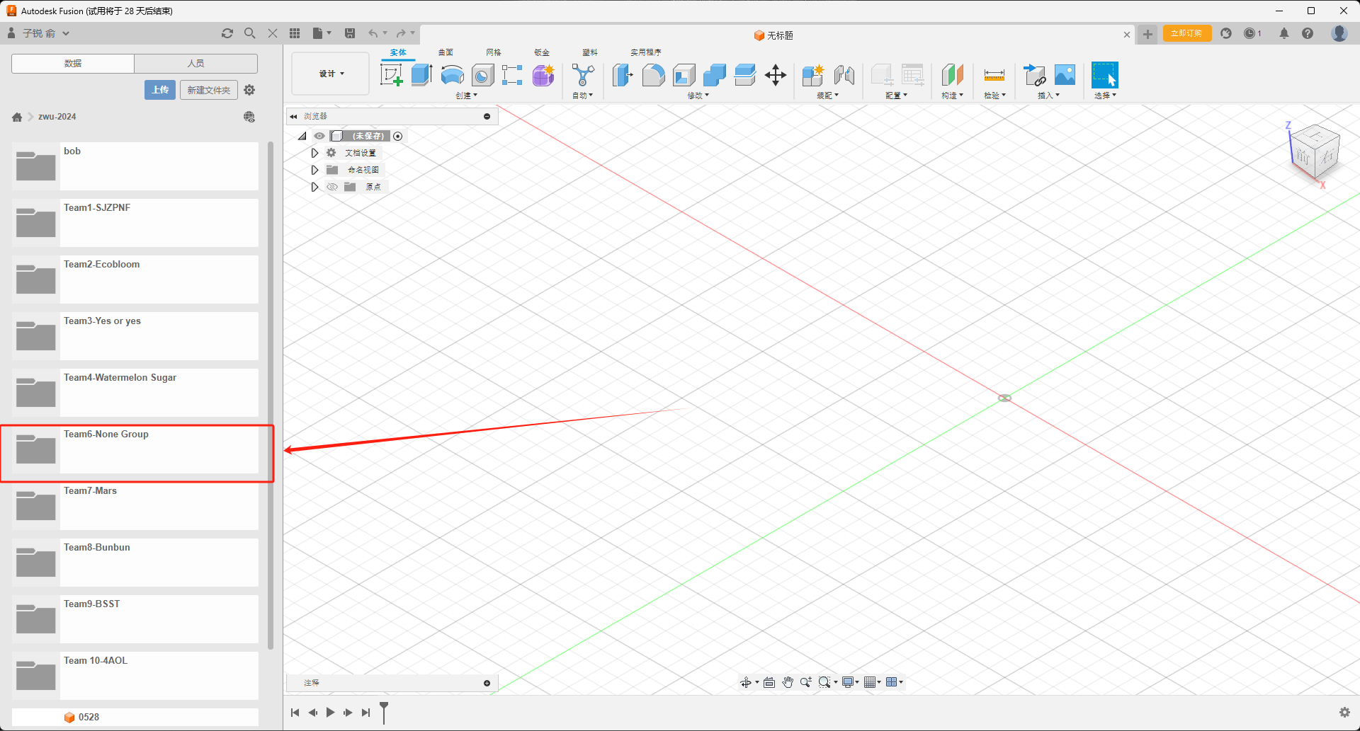
Find the folder location for your team in the project data on the left
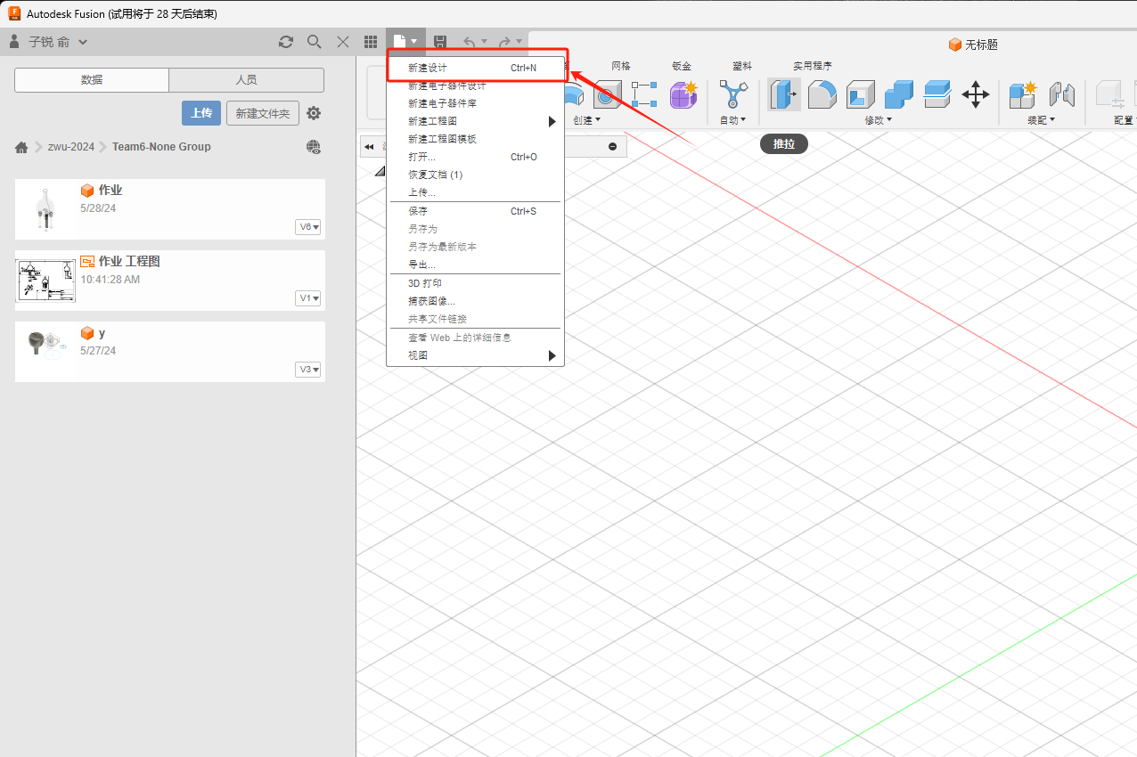
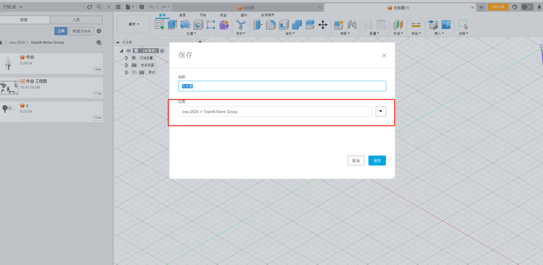
Create a new design and save it in the corresponding location
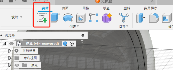
Select a new part
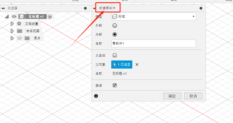
Use the tools inside to create a few simple parts
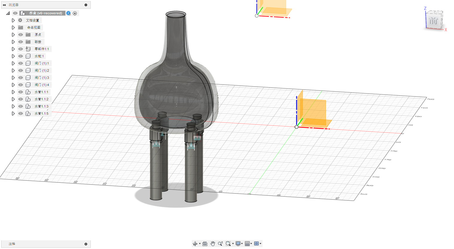
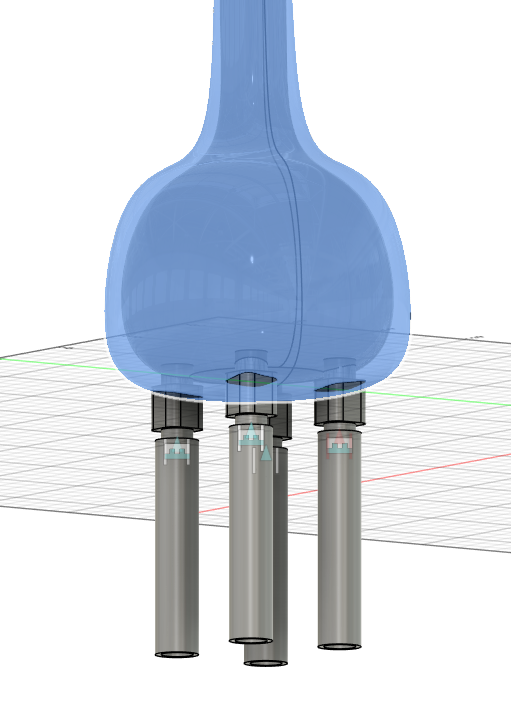
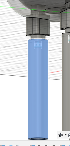
The design is divided into: bottle, solenoid valve, pipe these parts
The production process is simply divided into three steps, the first step is sketching
The software has many basic drawing tools for sketching
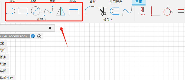
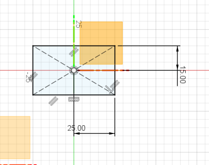
The sketch can be fully constrained after dimensioning or other constraints
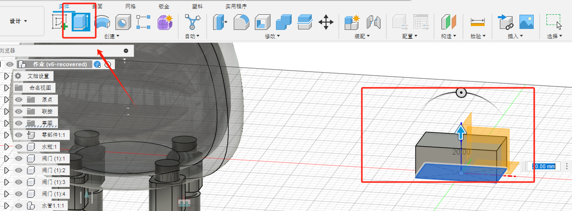
The second step is to use the create command to turn the sketch into a 3D model
It can be assembled after the two suitable parts have been created
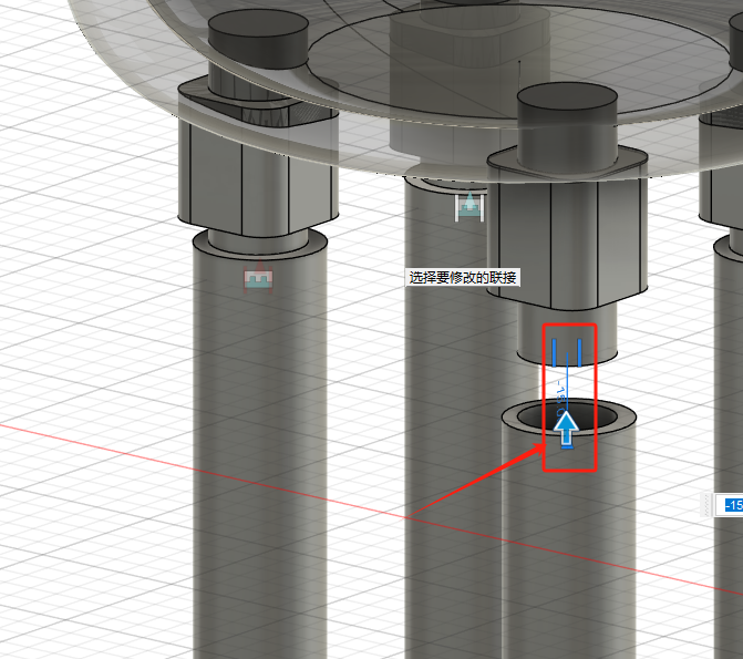
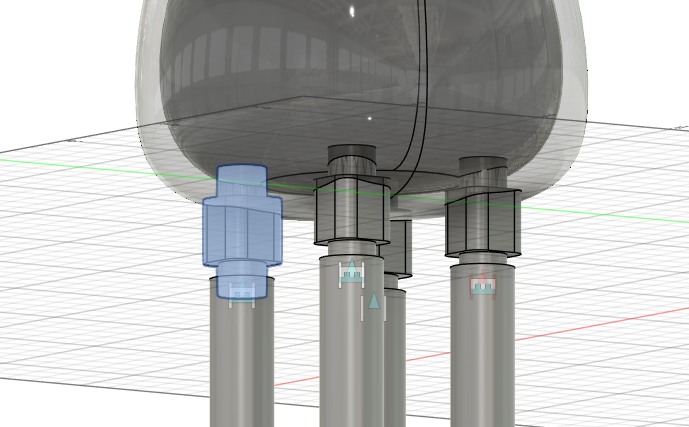
This is the motion state of the model
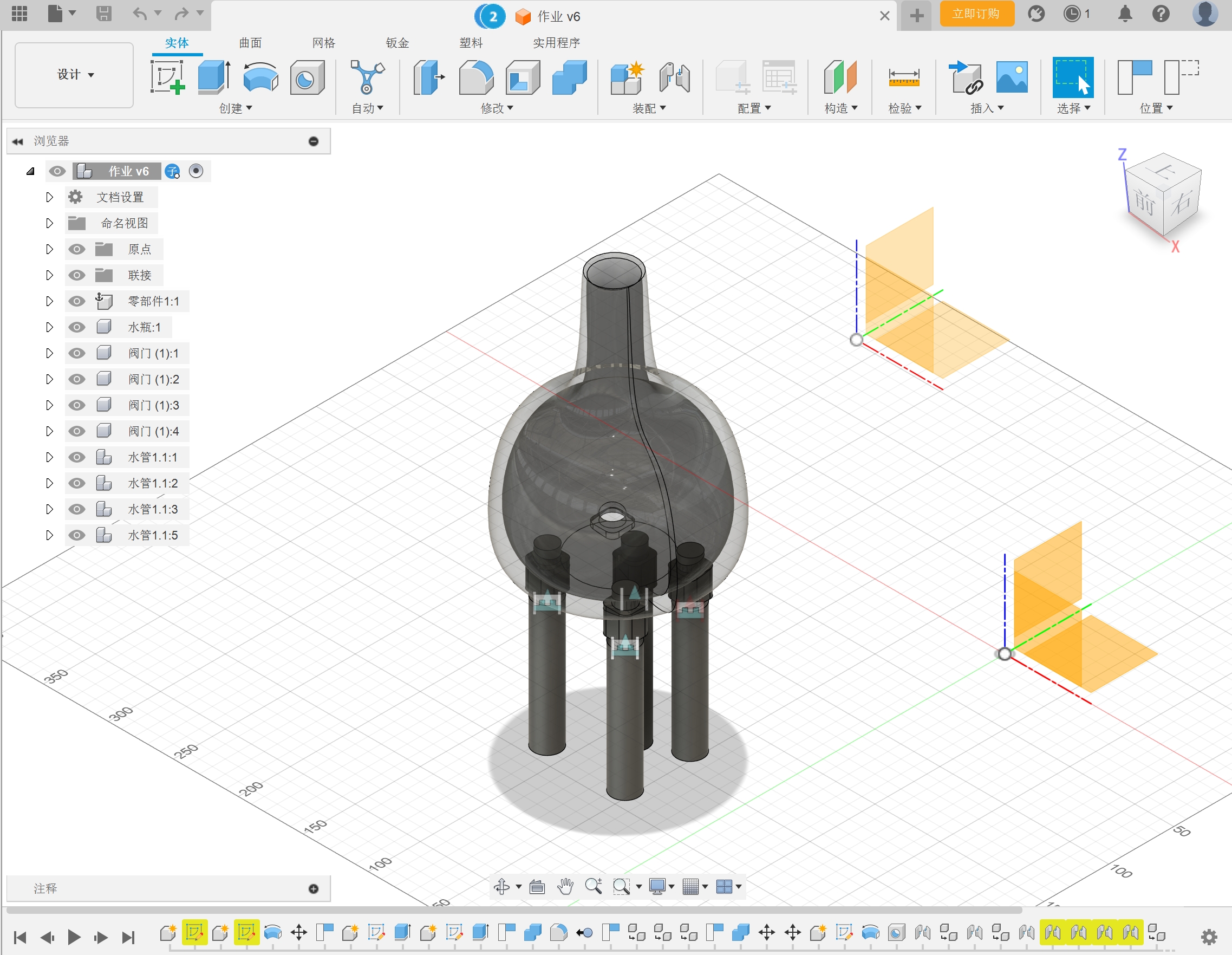
This is the historical construction record of the model
Simple parameter design history
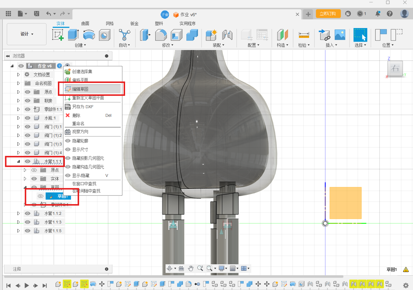
Step1 Click on the component to go to the edit sketch
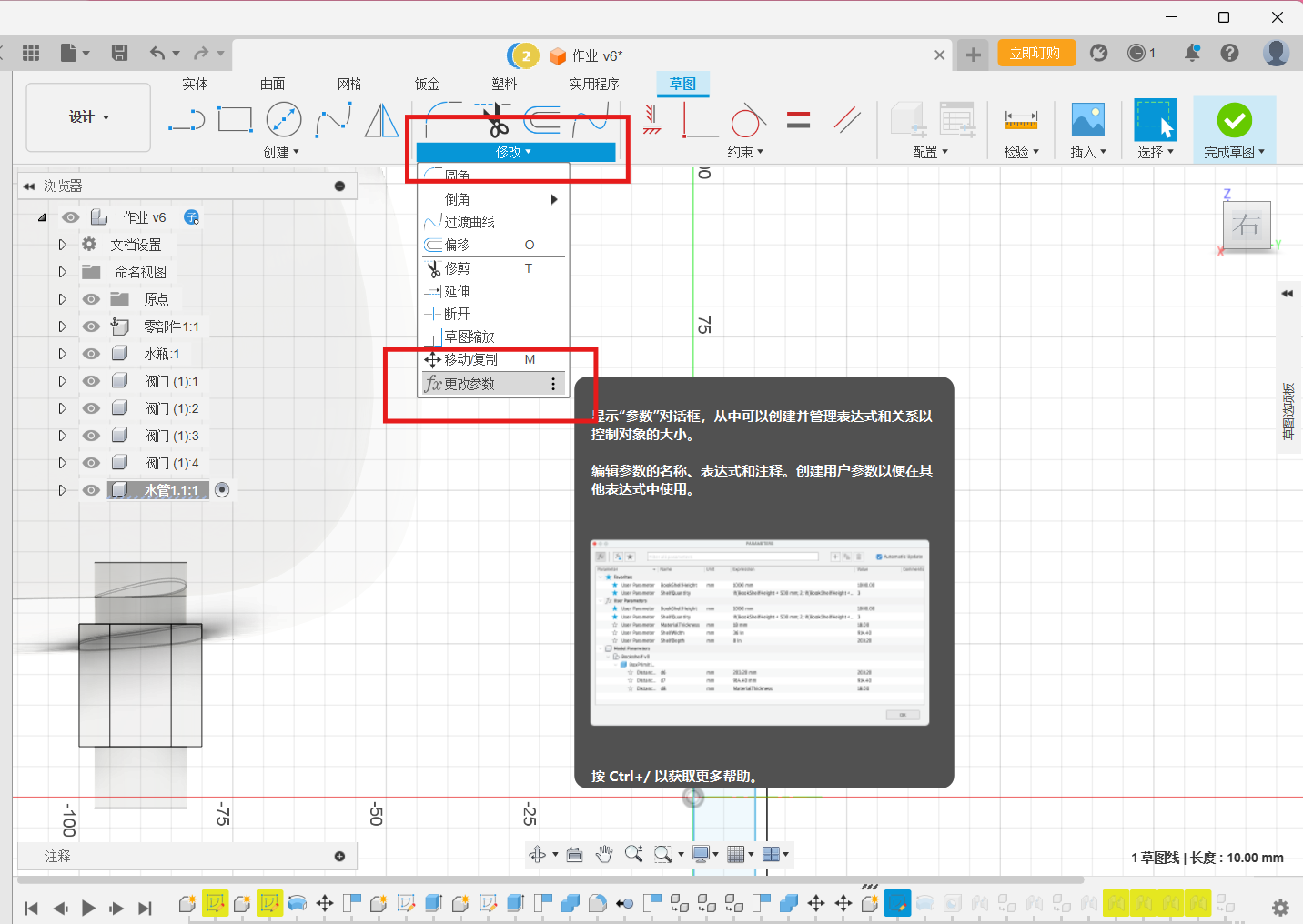
Step2 Click [Modify] - [Change Parameters]
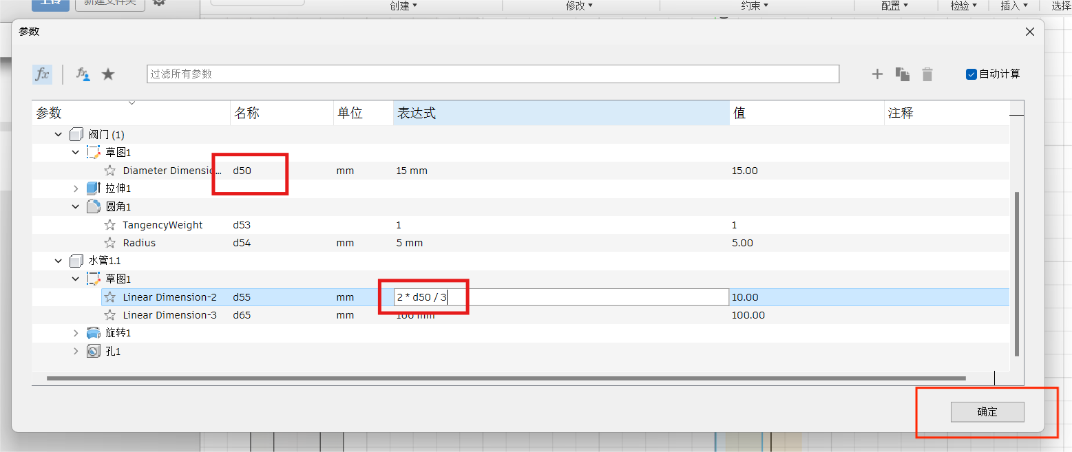
Step3 Find the name of the parameter to be used, find the parameter that needs to be changed, change it in the expression, and click OK
Creating an Engineering Drawing in Fusion 360
Find the folder location for your team in the project data on the left
Create a new design and save it in the corresponding location
Select a new part
Use the tools inside to create a few simple parts
The design is divided into: bottle, solenoid valve, pipe these parts
The production process is simply divided into three steps, the first step is sketching
The software has many basic drawing tools for sketching
The sketch can be fully constrained after dimensioning or other constraints
The second step is to use the create command to turn the sketch into a 3D model
It can be assembled after the two suitable parts have been created
This is the motion state of the model
This is the historical construction record of the model
Simple parameter design history
Step1 Click on the component to go to the edit sketch
Step2 Click [Modify] - [Change Parameters]
Step3 Find the name of the parameter to be used, find the parameter that needs to be changed, change it in the expression, and click OK
Creating an Engineering Drawing in Fusion 360
This guide provides a basic overview of creating engineering drawings with Fusion 360.
1. Open Your Fusion 360 Model
Launch Fusion 360 and open the model you wish to create an engineering drawing for.
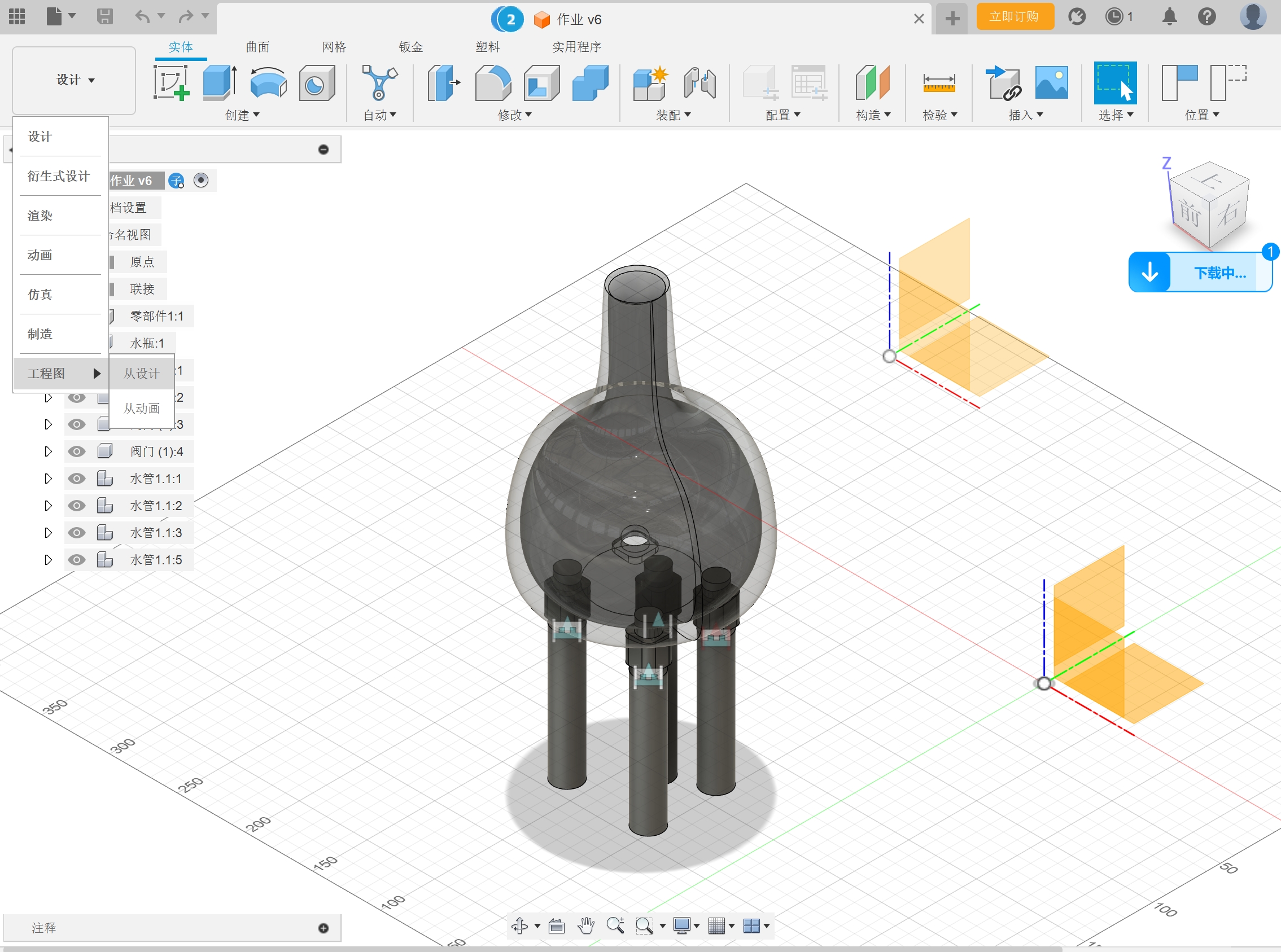
2. Accessing Engineering Drawing Mode
Click on "Design" and then select "Drawing" - "From Design" to initiate the creation of the engineering drawing.
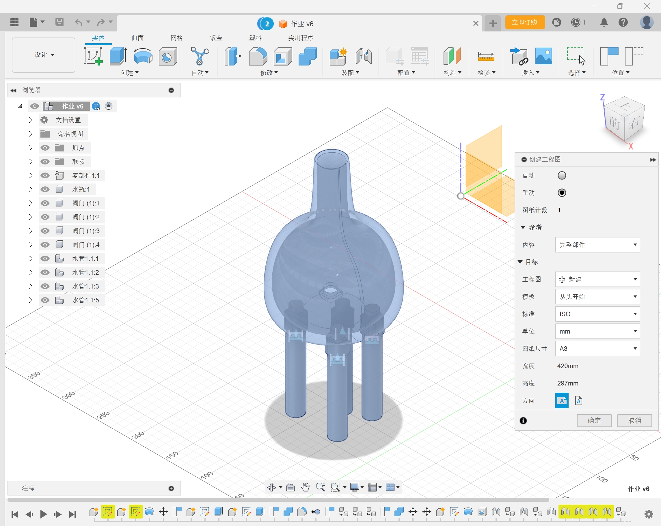
3. Creating the Engineering Drawing
In the creation interface, select the desired unit size and other preferences suited for your drawing requirement.
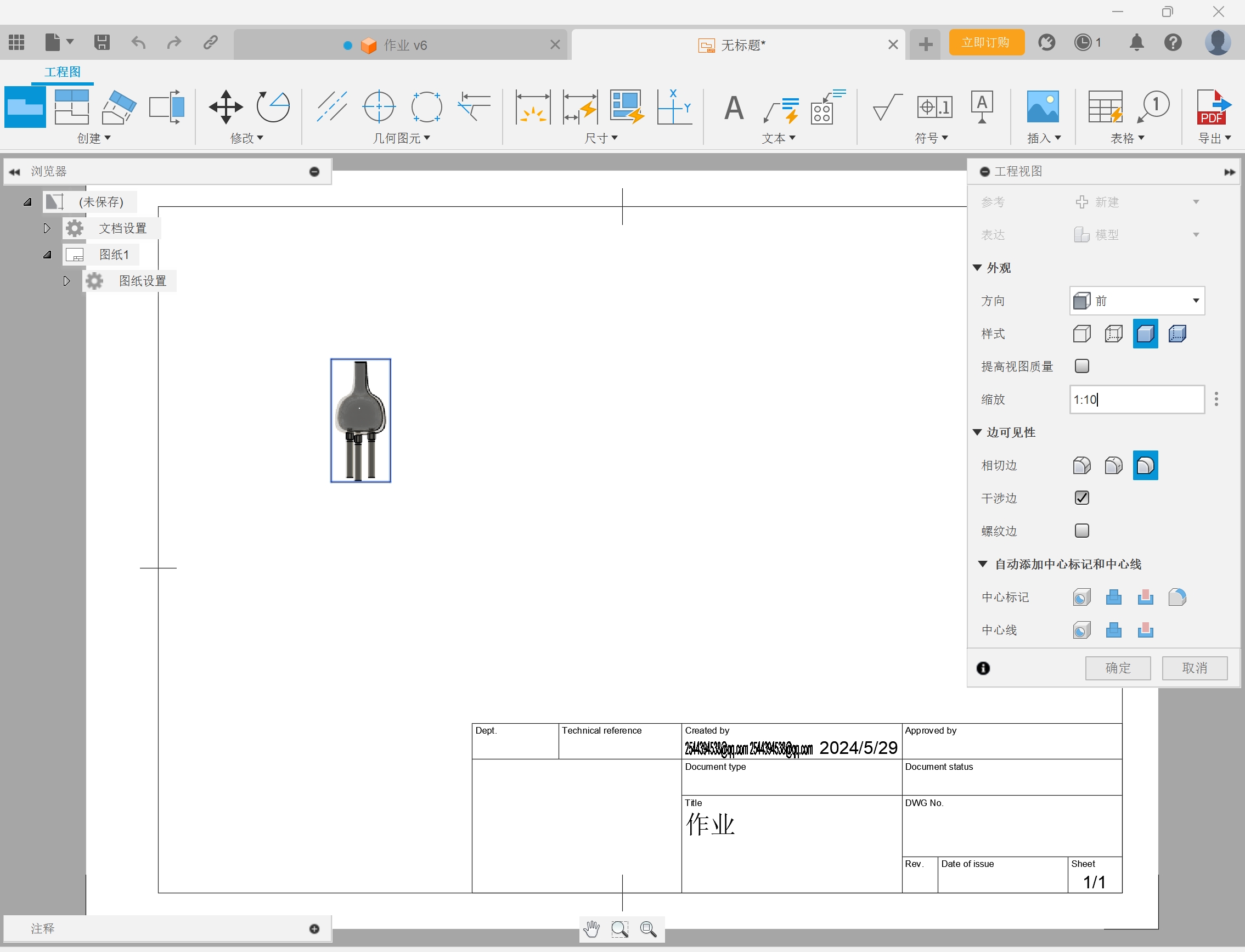
4. Positioning the Model
Position your model within the drawing, adjusting the zoom and orientation to suit the needs of your drawing.
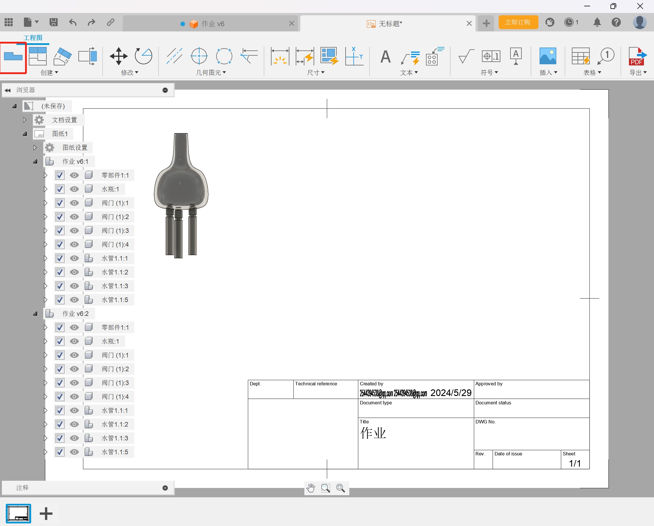
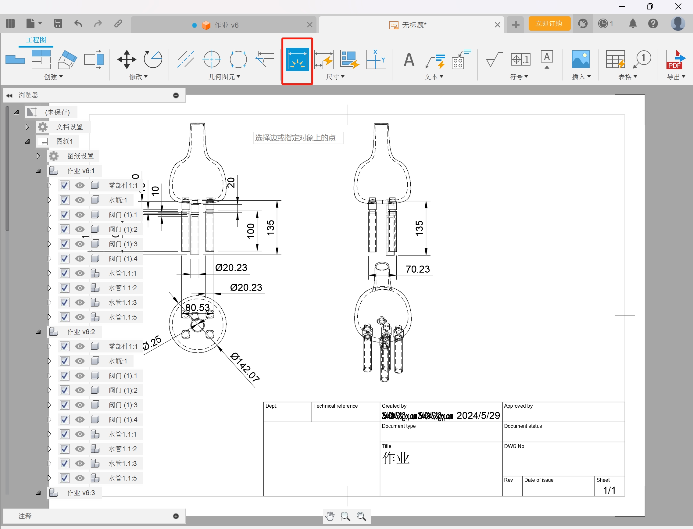
5. Adding New Views
Use the button in the top-left corner to add new views of your model to the drawing.
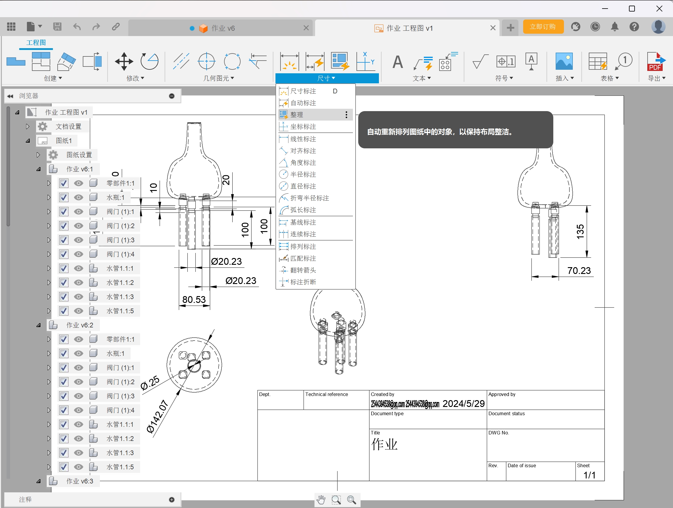
6. Dimensioning
Use the "Dimension" tool to annotate your drawing with the correct sizes.
7. Organizing Dimensions
Arrange and clean up the layout of dimensions to ensure your drawing is clear and understandable.
Note: This guide is a simplified overview. For comprehensive tutorials and advanced features, please refer to the official Fusion 360 documentation and tutorials.
Simple introduce another CAD software or experience
Solidworks

SolidWorks is a comprehensive 3D mechanical design solution developed by Dassault Systemes for a wide range of applications in mechanical engineering, industrial design, product design and more.

Features
a.Parametric design: SolidWorks takes a parametric modeling approach, meaning that every feature in a design is defined based on size and geometric constraints. Changing these parameters automatically updates the entire model and is ideal for design processes that require frequent iterations.
b.Ease of use: SolidWorks has an intuitive interface, a relatively flat learning curve, and plenty of tutorials and resources to help new users get started quickly. It also supports drag and drop, making the design more straightforward and efficient. c.Comprehensive feature set: In addition to basic 3D modeling, SolidWorks integrates motion Simulation, stress analysis (through its built-in simulation tool), piping and wiring, rendering (PhotoView 360), and data management to cover almost the entire product development process. d.Compatibility and extensibility: Supports interaction with a variety of other CAD software and file formats, such as STEP, IGES, DWG, etc. In addition, through its API (Application Programming Interface), users can develop custom plug-ins to meet specific needs. e.PDM (Product Data Management) Integration: SolidWorks PDM helps teams manage and track design data, version control, and facilitate collaboration between teams.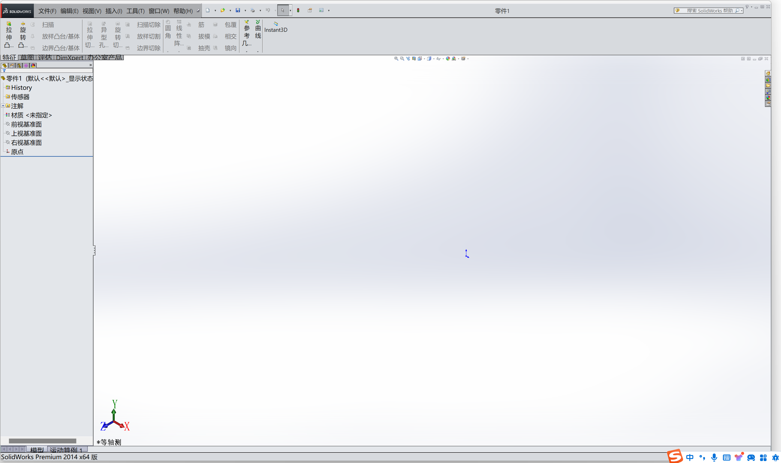
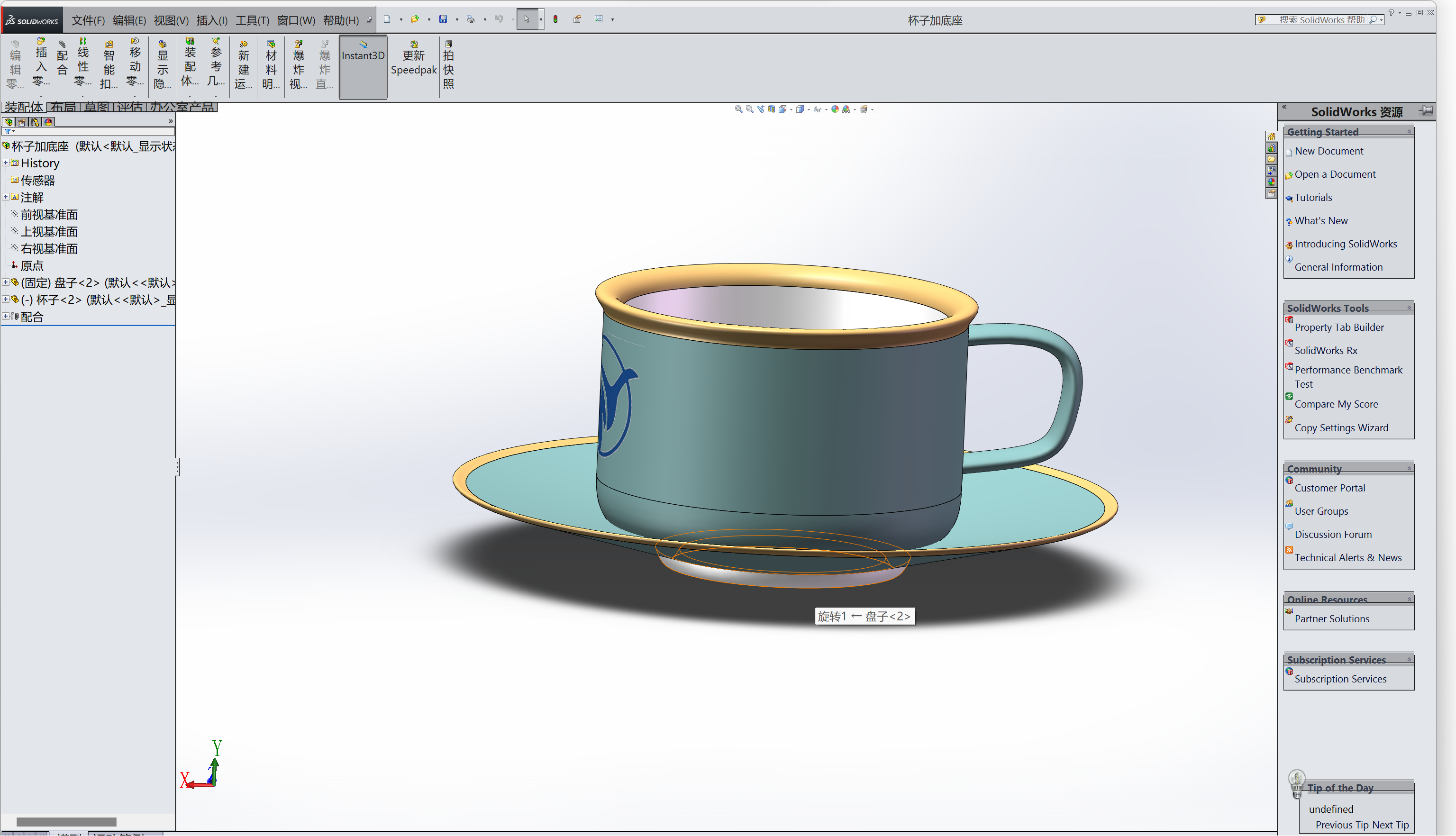
Experience:
Users often report that SolidWorks is very strong in mechanical design, especially when it comes to creating complex assemblies and documenting detailed engineering drawings. Its user interface is friendly and efficient, especially for users who are used to Windows environments. However, as with any professional-grade software, it may take time and practice to fully master all the advanced features. Some users may find that their demands on system resources are high, especially when dealing with large assemblies or complex simulations. Overall, SolidWorks has a strong reputation within the CAD community for its powerful capabilities, extensive industry applications, and active user community.
Plugins
There are many plugins and extensions that can be found in the plugins library. Our group does not use plugins so this is just an introduction
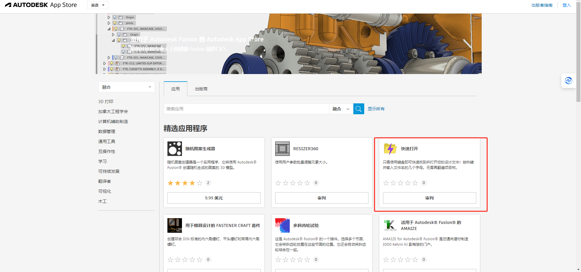
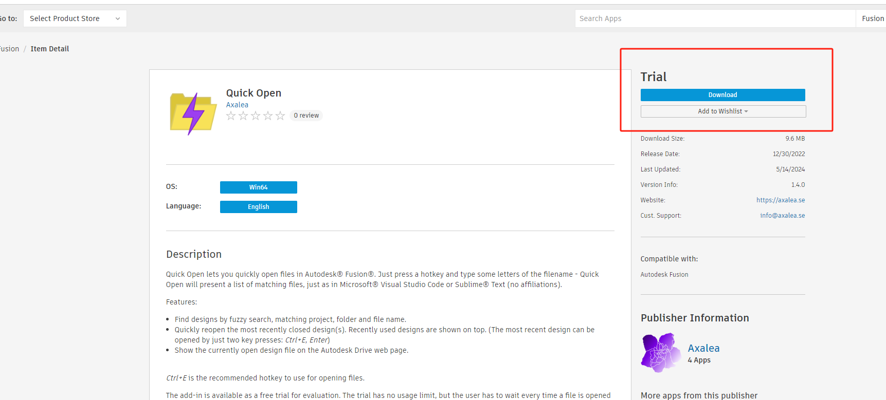
Use the plugins
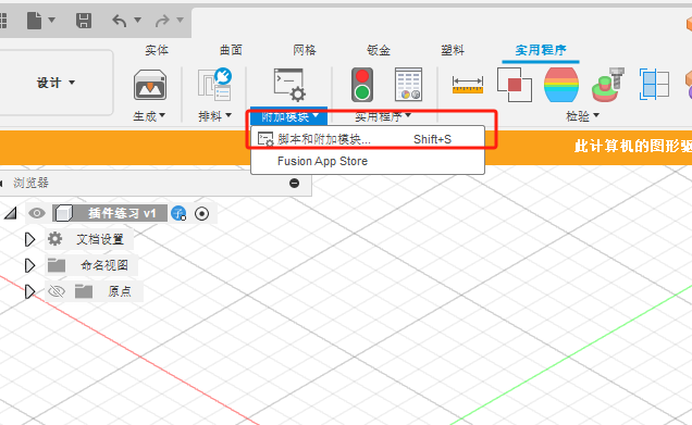
Click and select to use
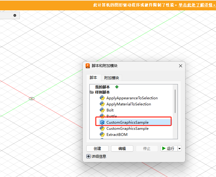
Parts can be created using plug-ins
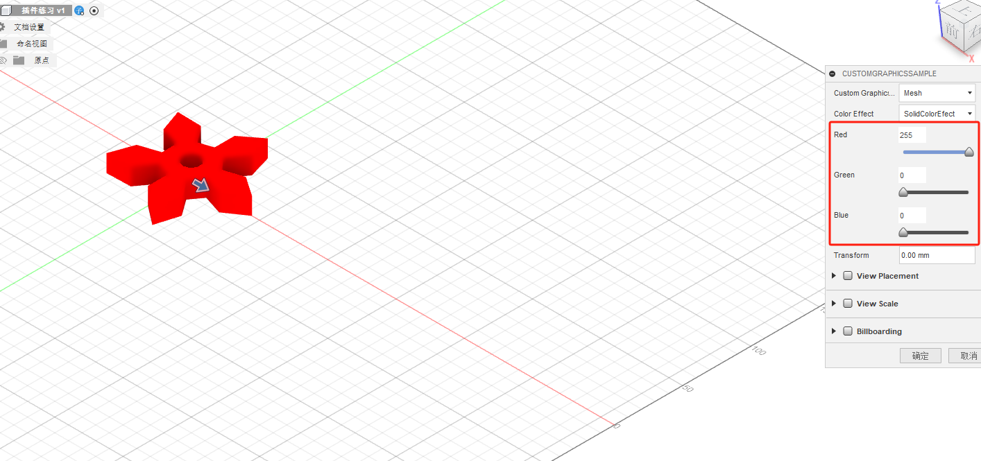
Here you can select the type, such as: grid, wire frame, and so on
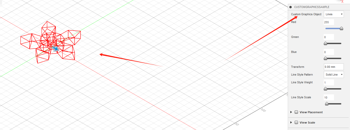
Practice for Automated Modeling
Click and select to use
Parts can be created using plug-ins
Here you can select the type, such as: grid, wire frame, and so on
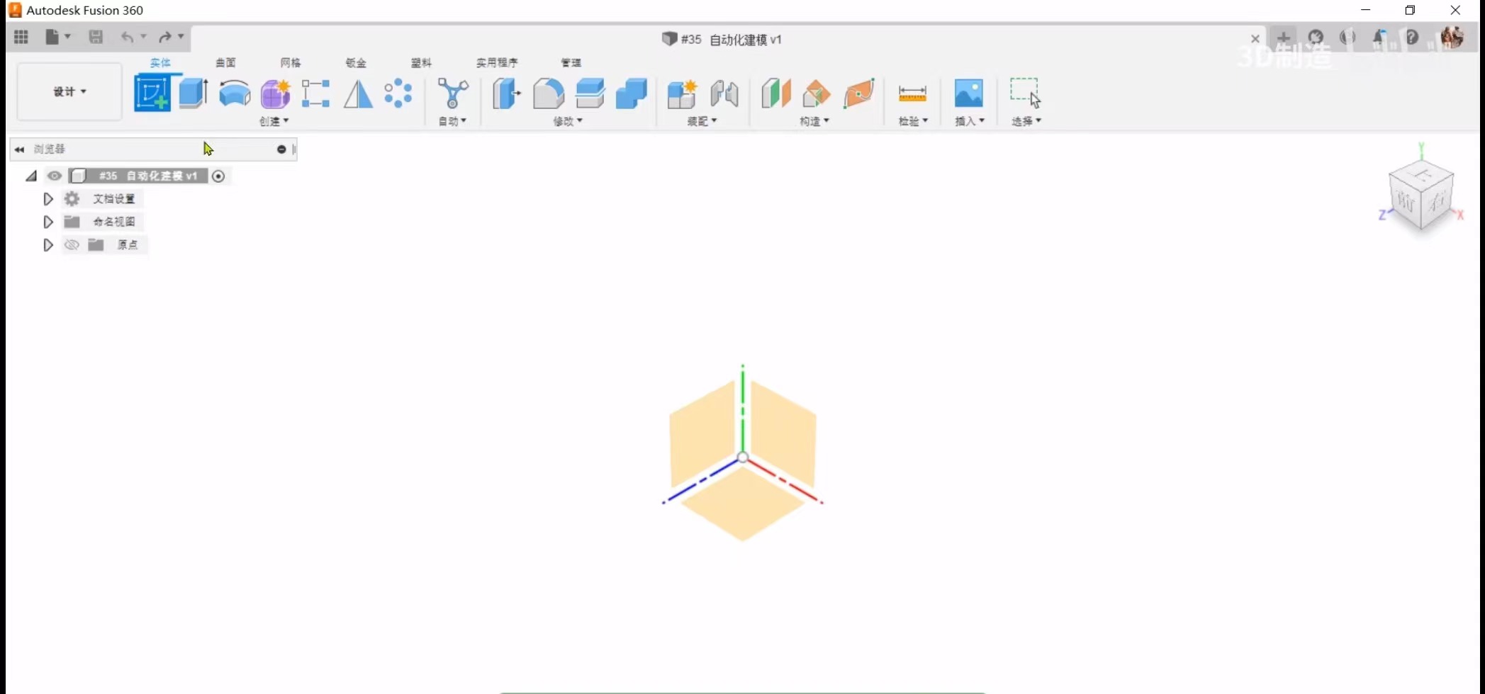
Practice for Automated Modeling
Here you can select the type, such as: grid, wire frame, and so on
Practice for Automated Modeling
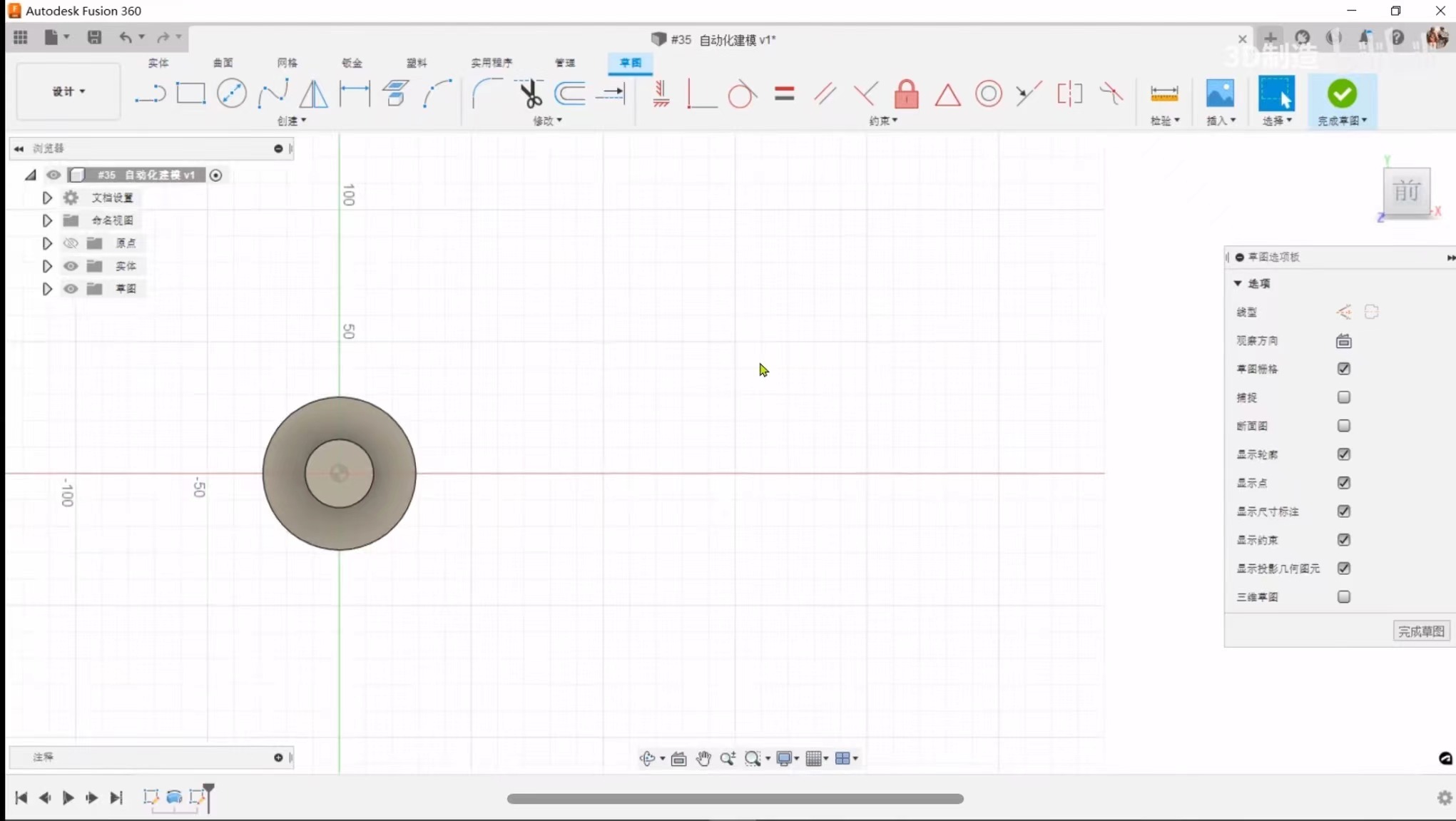
Step 1: Create sketch
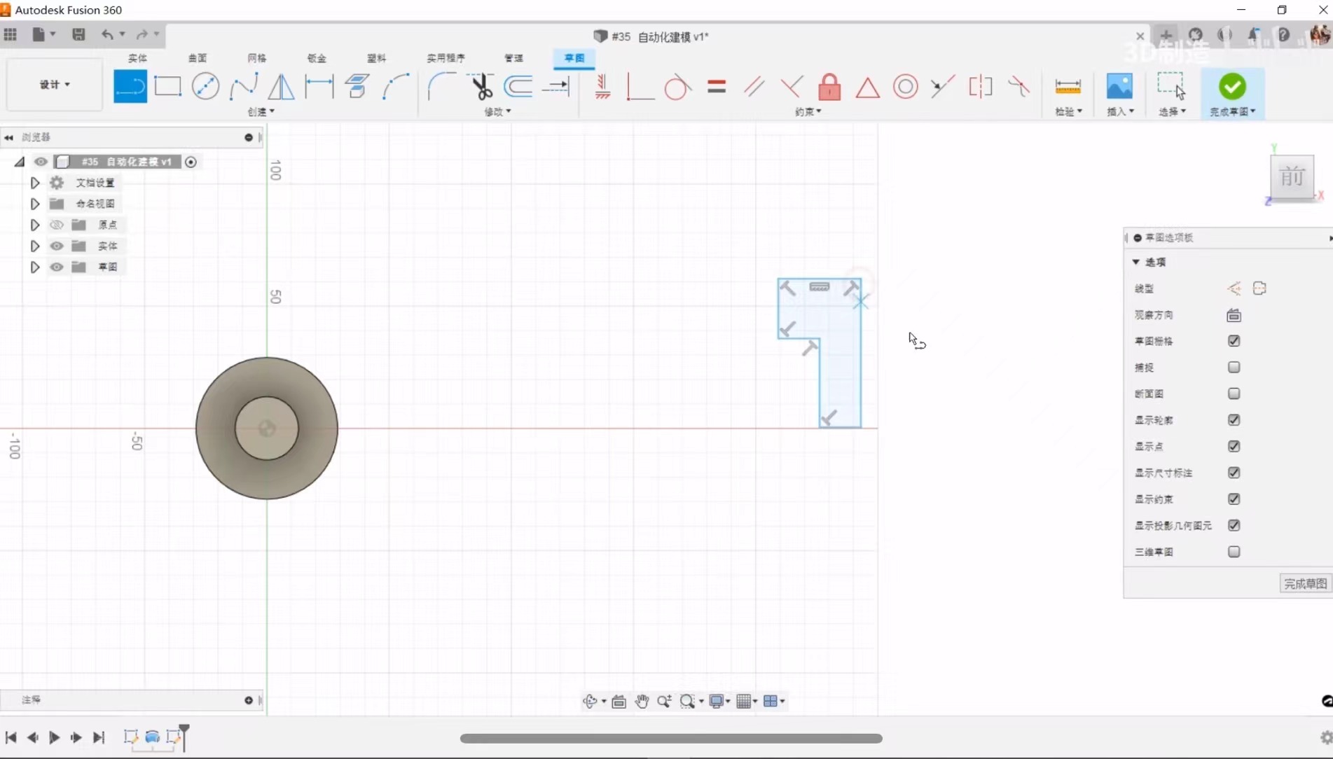
Step 2: Construction
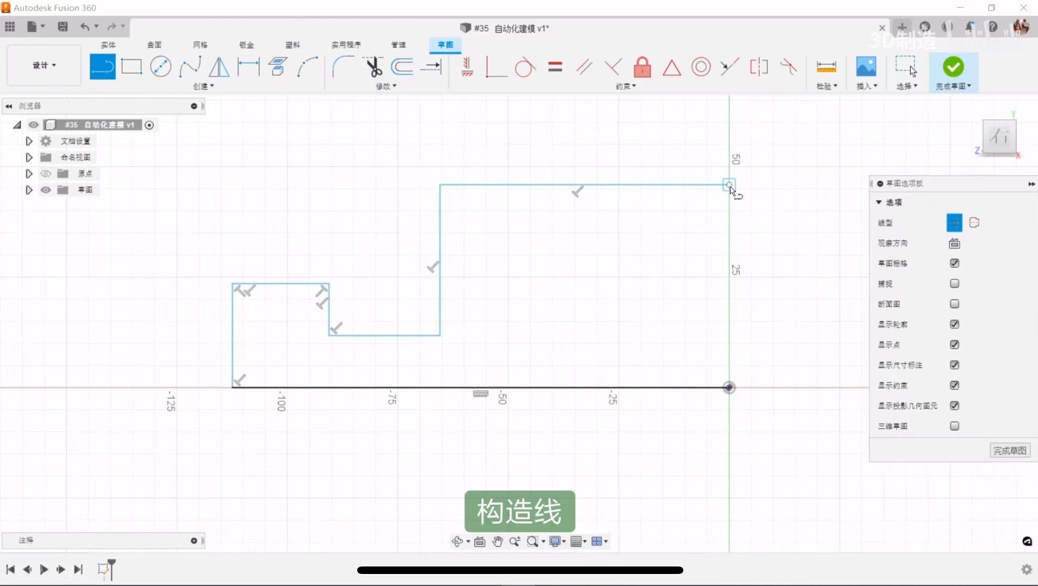
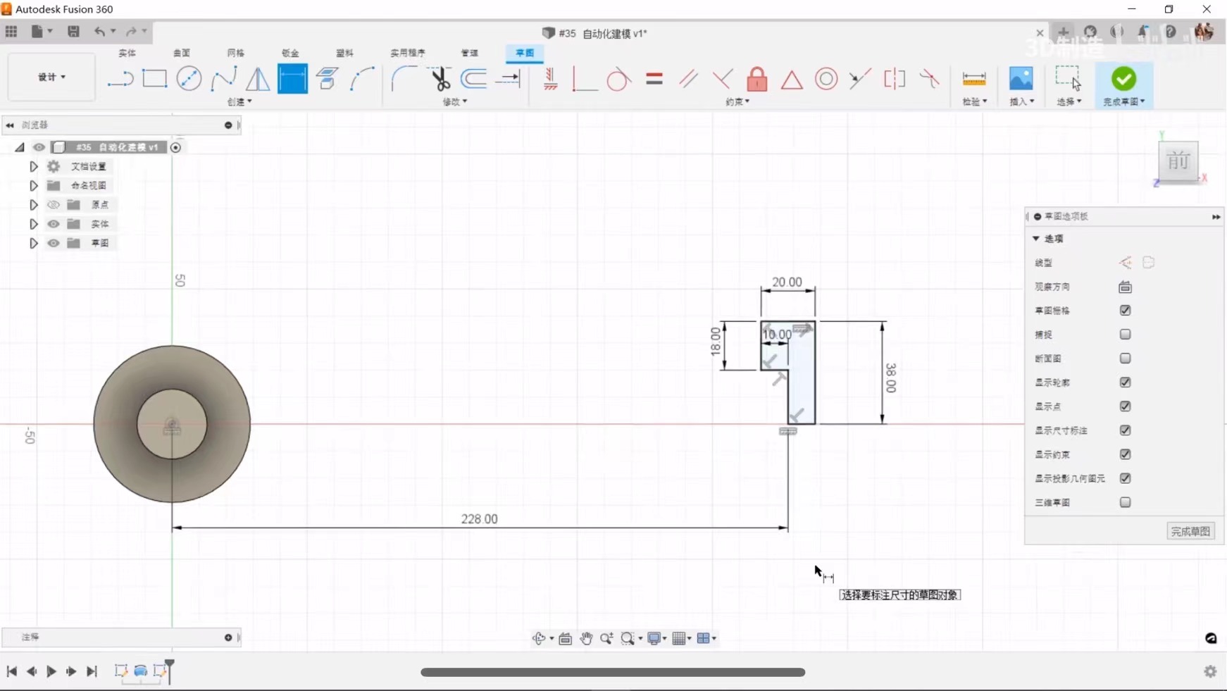
Step 3: Label size
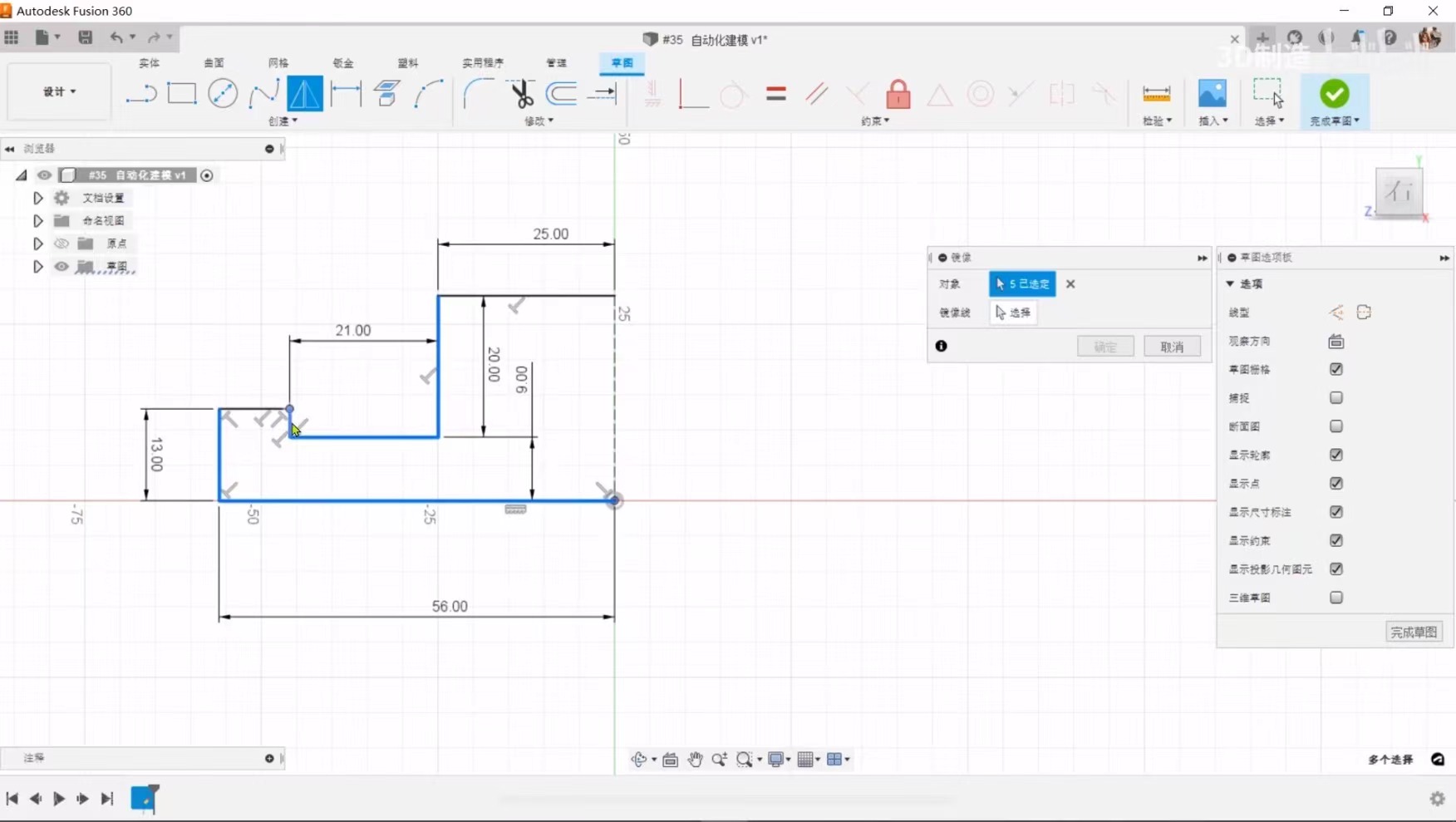
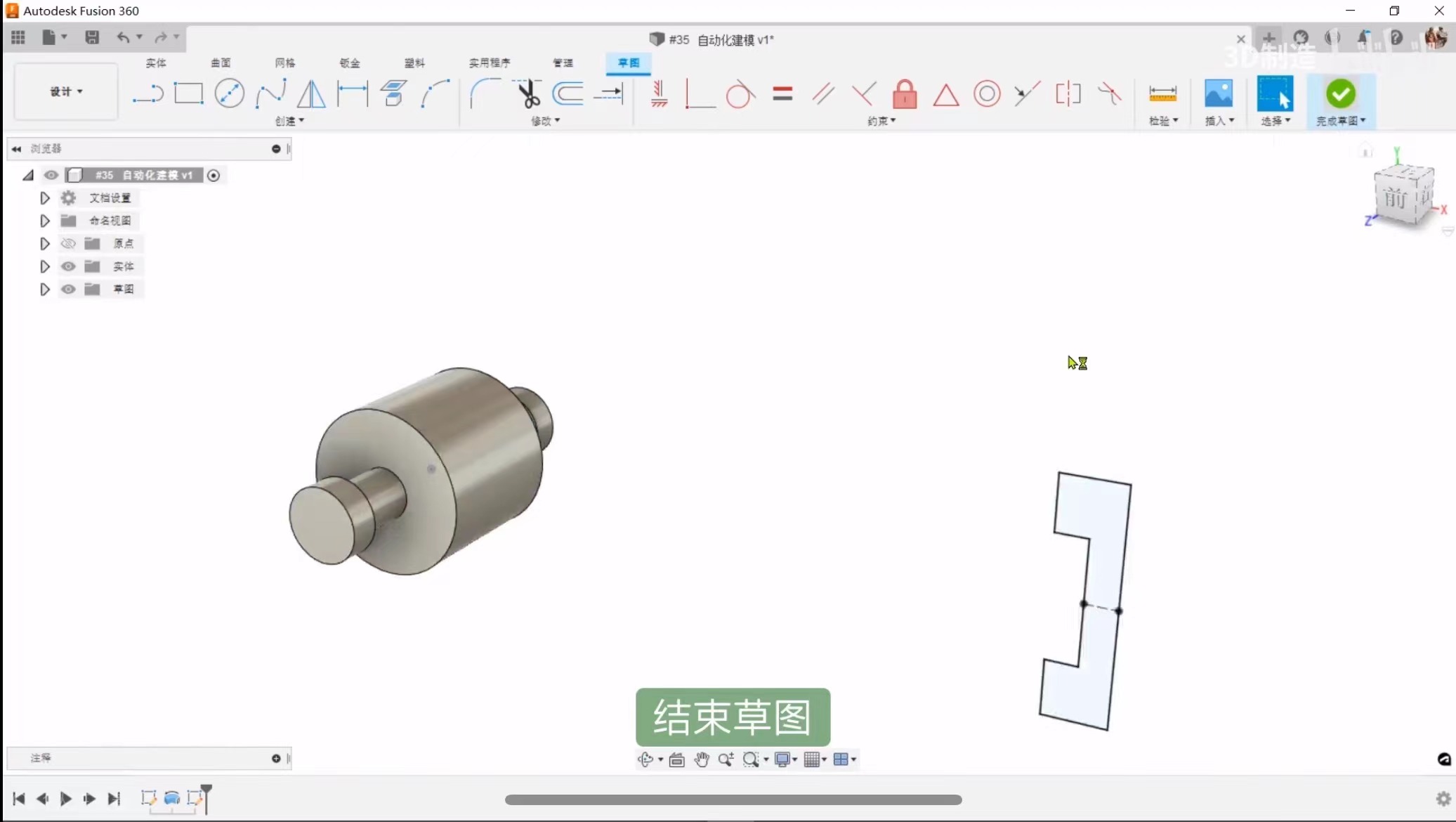
Step 4: Create mirror image
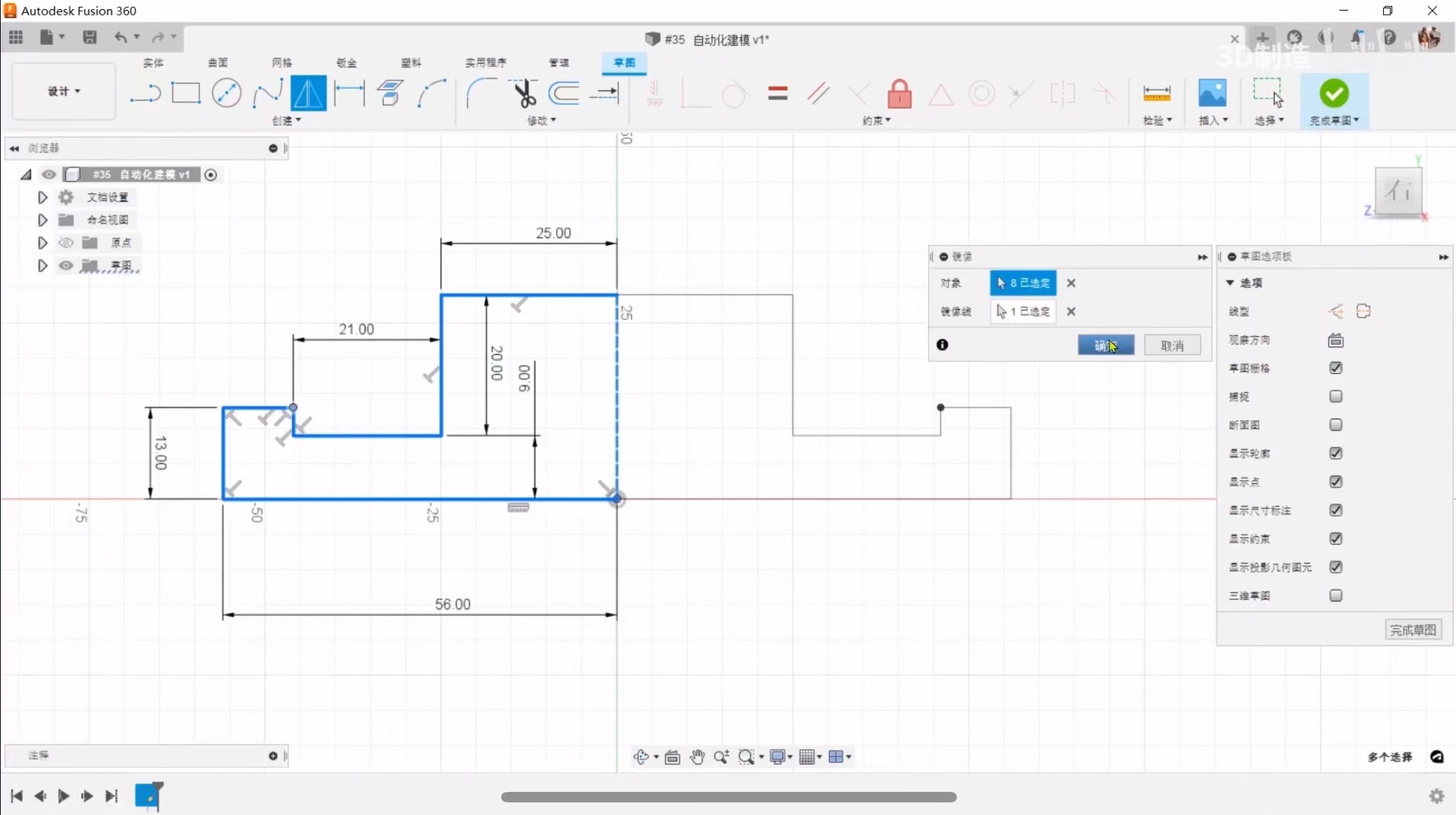
Step 5: End sketch
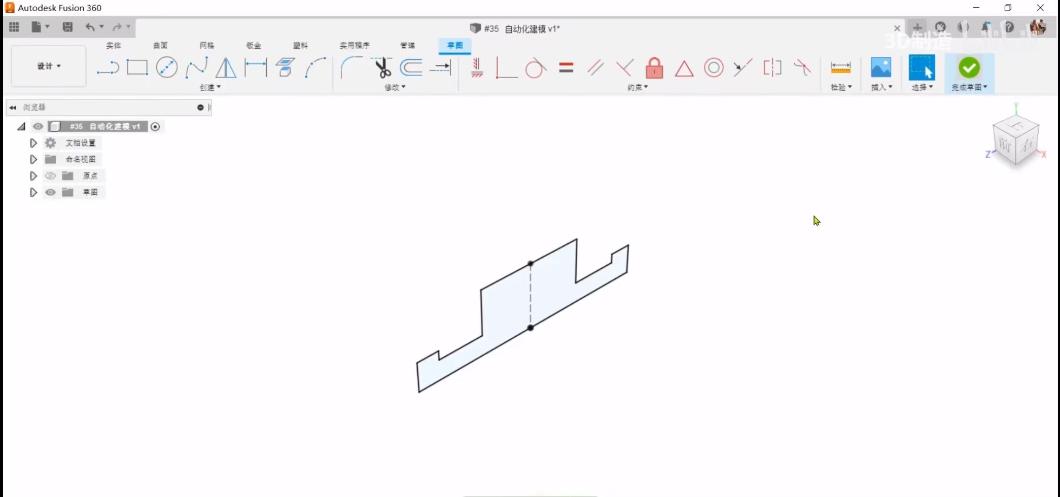
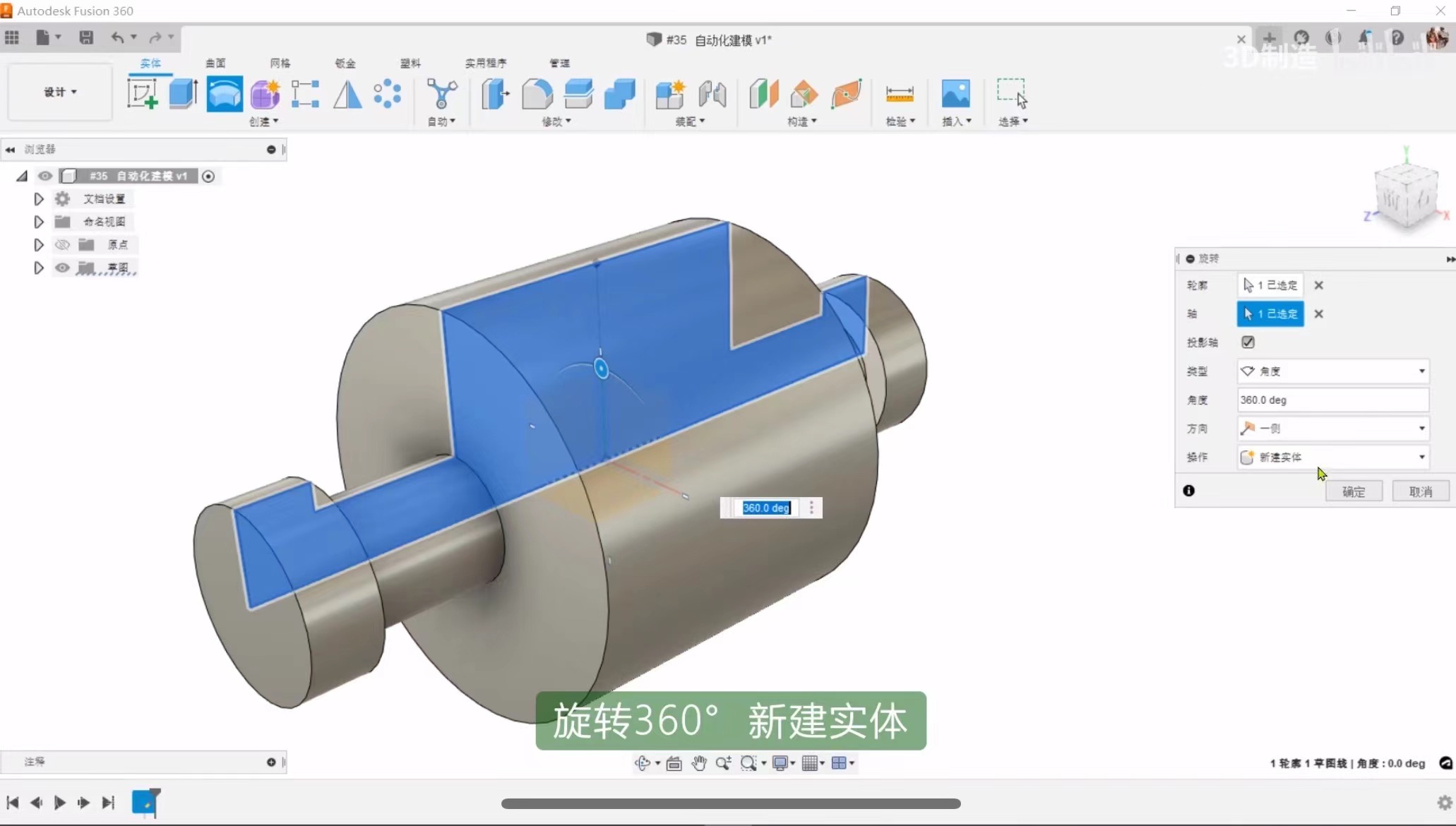
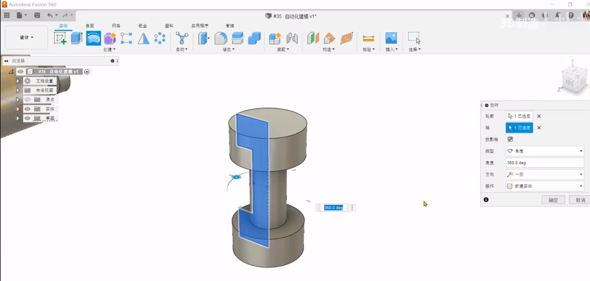
Step 6: Rotate 360 degrees to create a new entity
Step 7: Create sketch
Step 8: Construction
Step 9: Label size and restrict
Step 10: End sketch
Step 11: Rotate 360 degrees to create a new entity
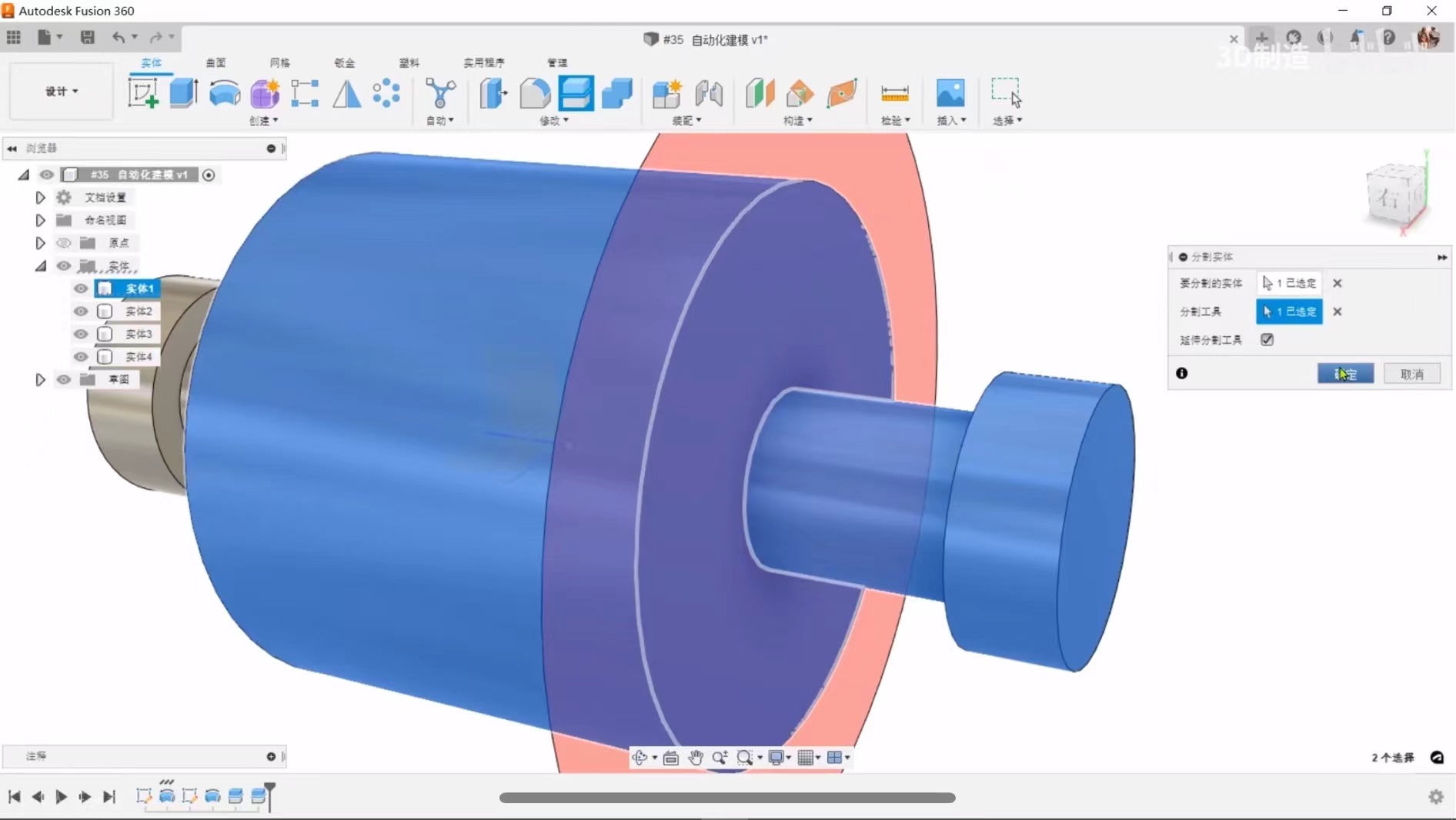
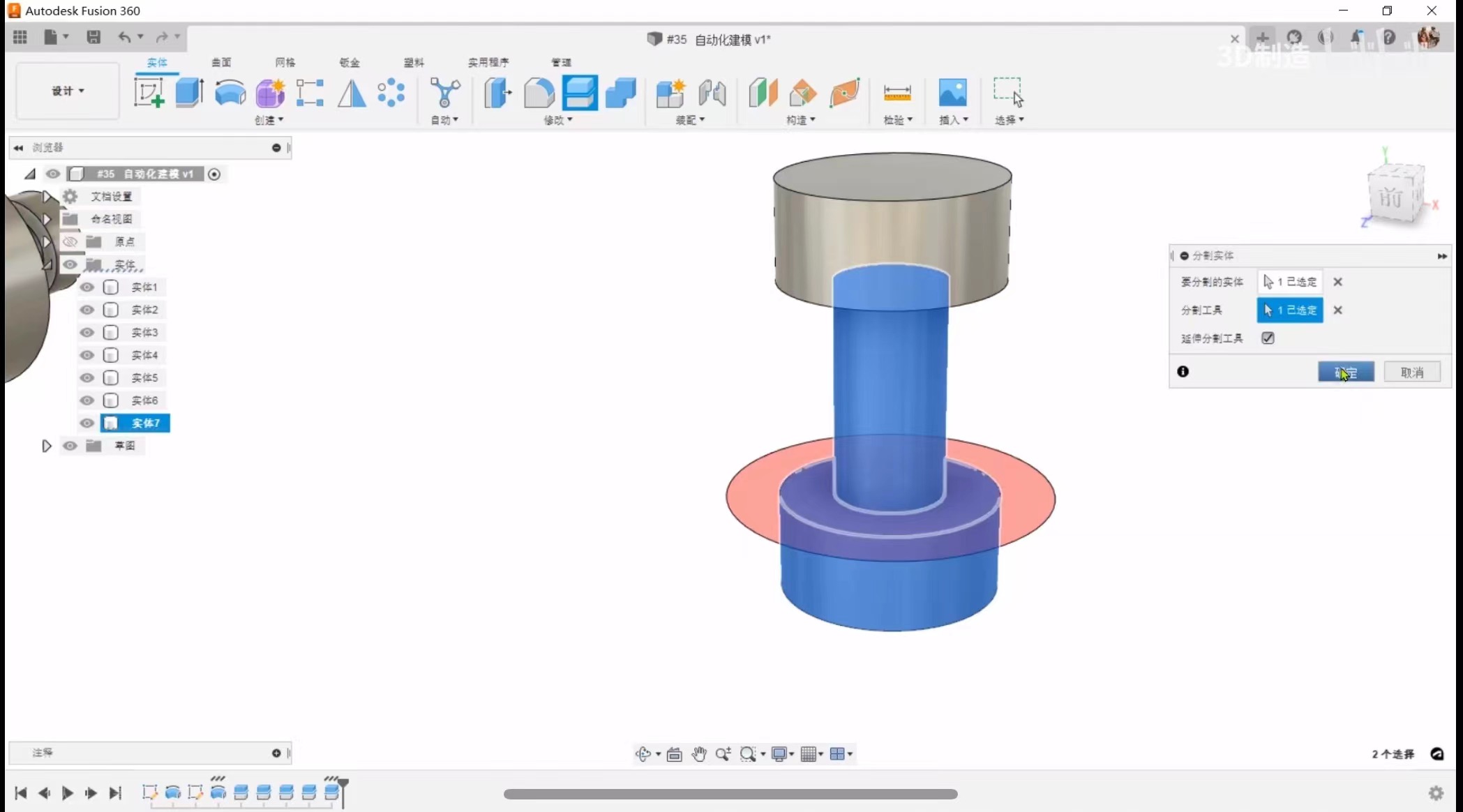
Step 12: Because the connecting surface and obstacle are the same entity and cannot be recognized, the connecting surface and obstacle are separated into separate entities
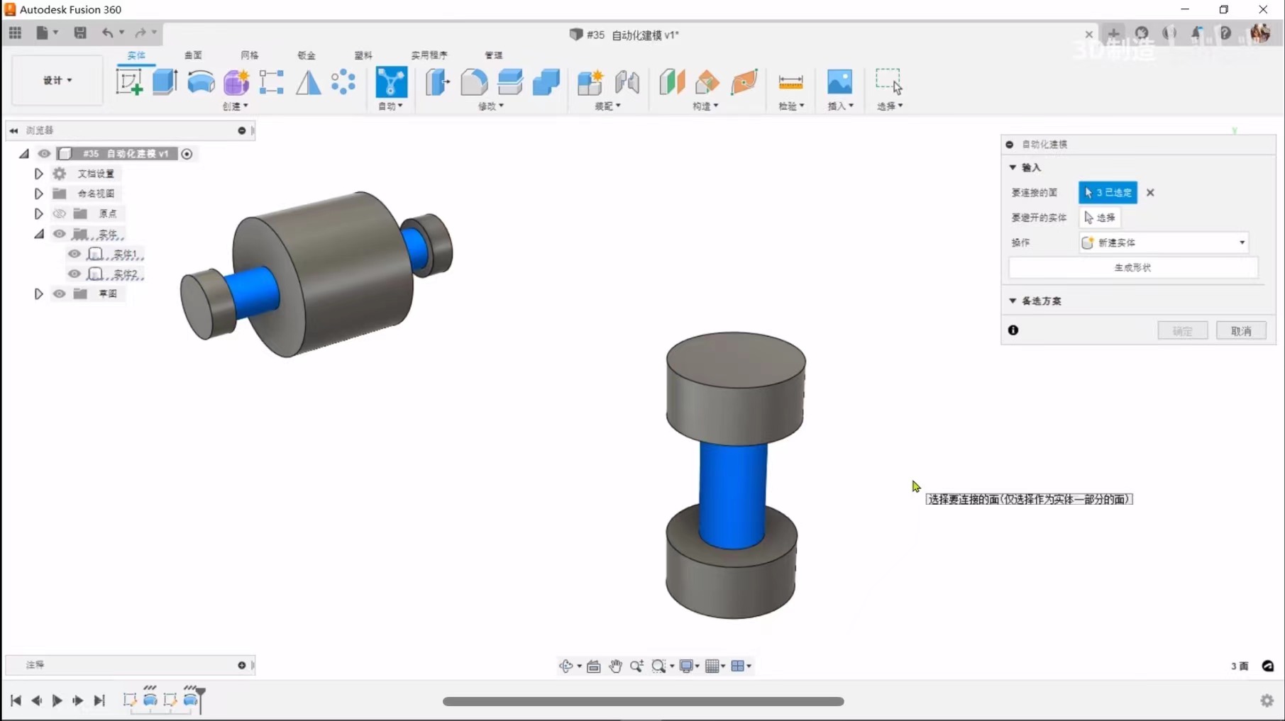
Step 13: Select automated modeling
Step 14: Select the faces to connect
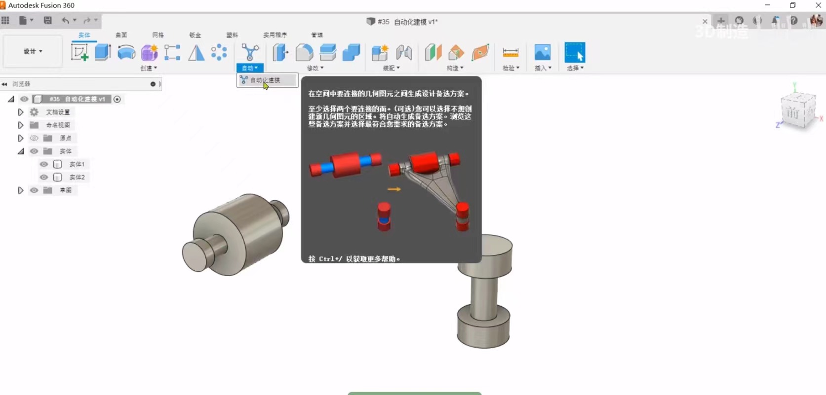
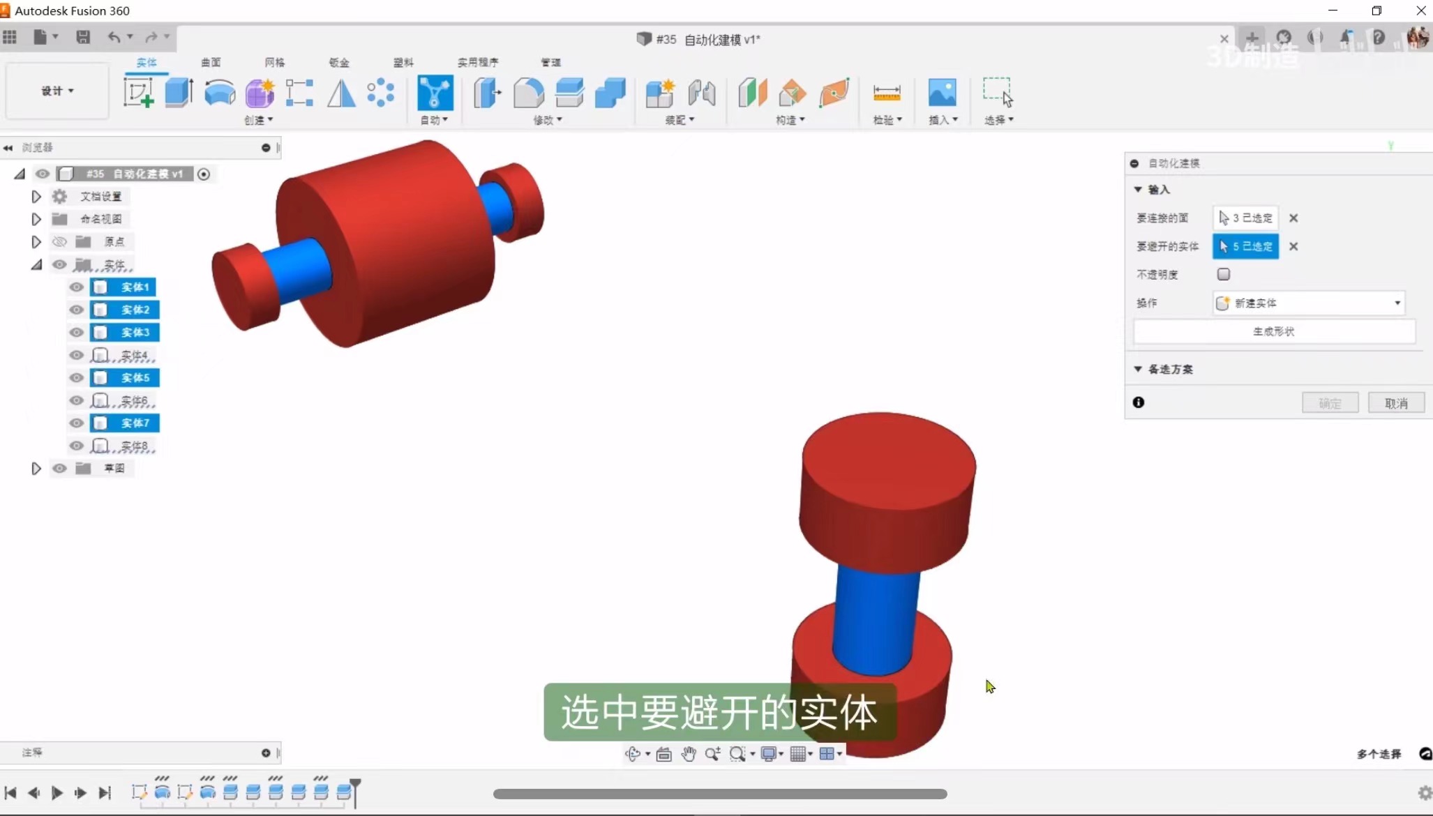
Step 15: Select entities to avoid
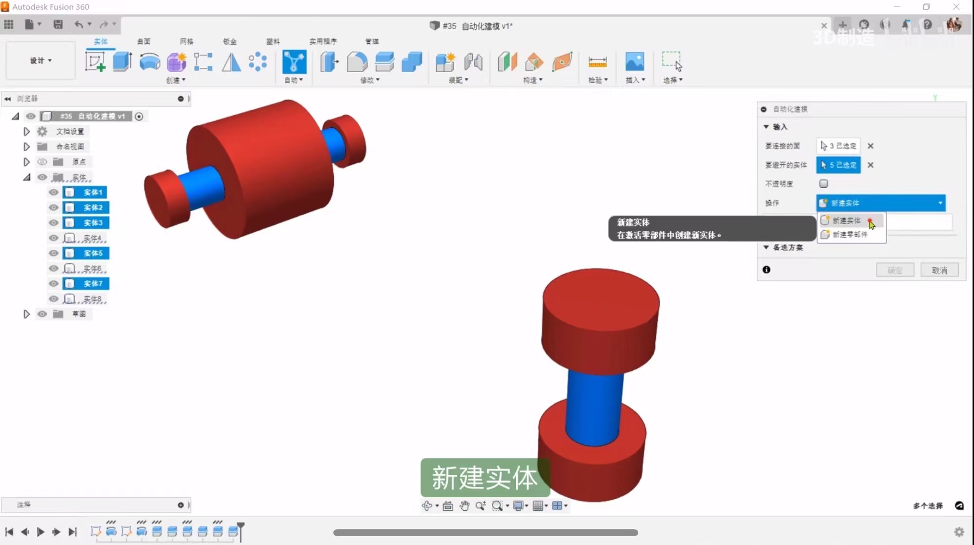
Step 16: Create a new entity
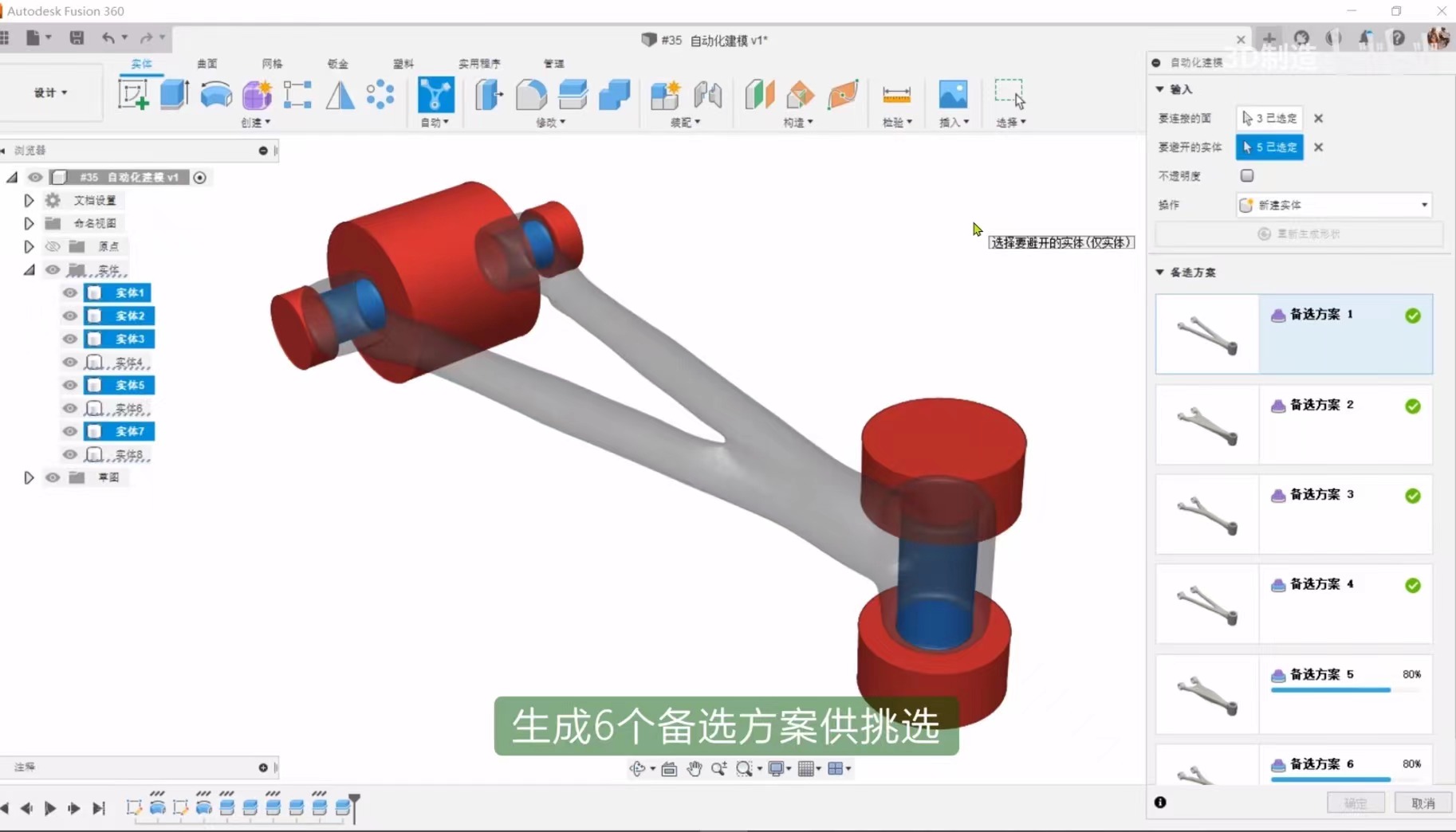
Step 17: Generate several alternative solutions
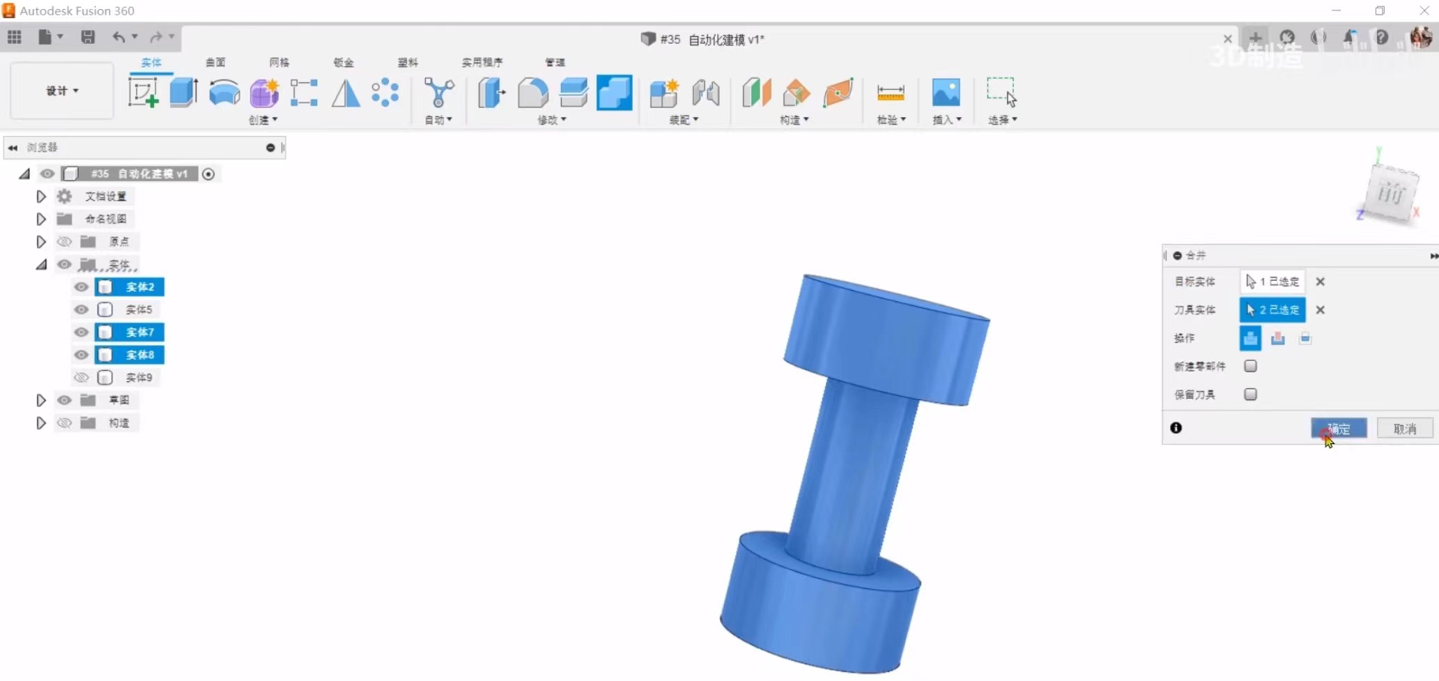
Step 18: Merging entities
Step 19: Chamfer
Show
 From Bilibili