3D Printer
Introduction
3D printing or additive manufacturing is the construction of a three-dimensional object from a CAD model or a digital 3D model. It can be done in a variety of processes in which material is deposited, joined or solidified under computer control,with the material being added together (such as plastics, liquids or powder grains being fused), typically layer by layer.
Applications of 3D Printing Technology
In Construction
With the introduction of 3D printing technologies, the construction industry is on the verge of a revolution. 3D printing is set to redefine the future of construction, from building homes in record time to creating complex architectural structures.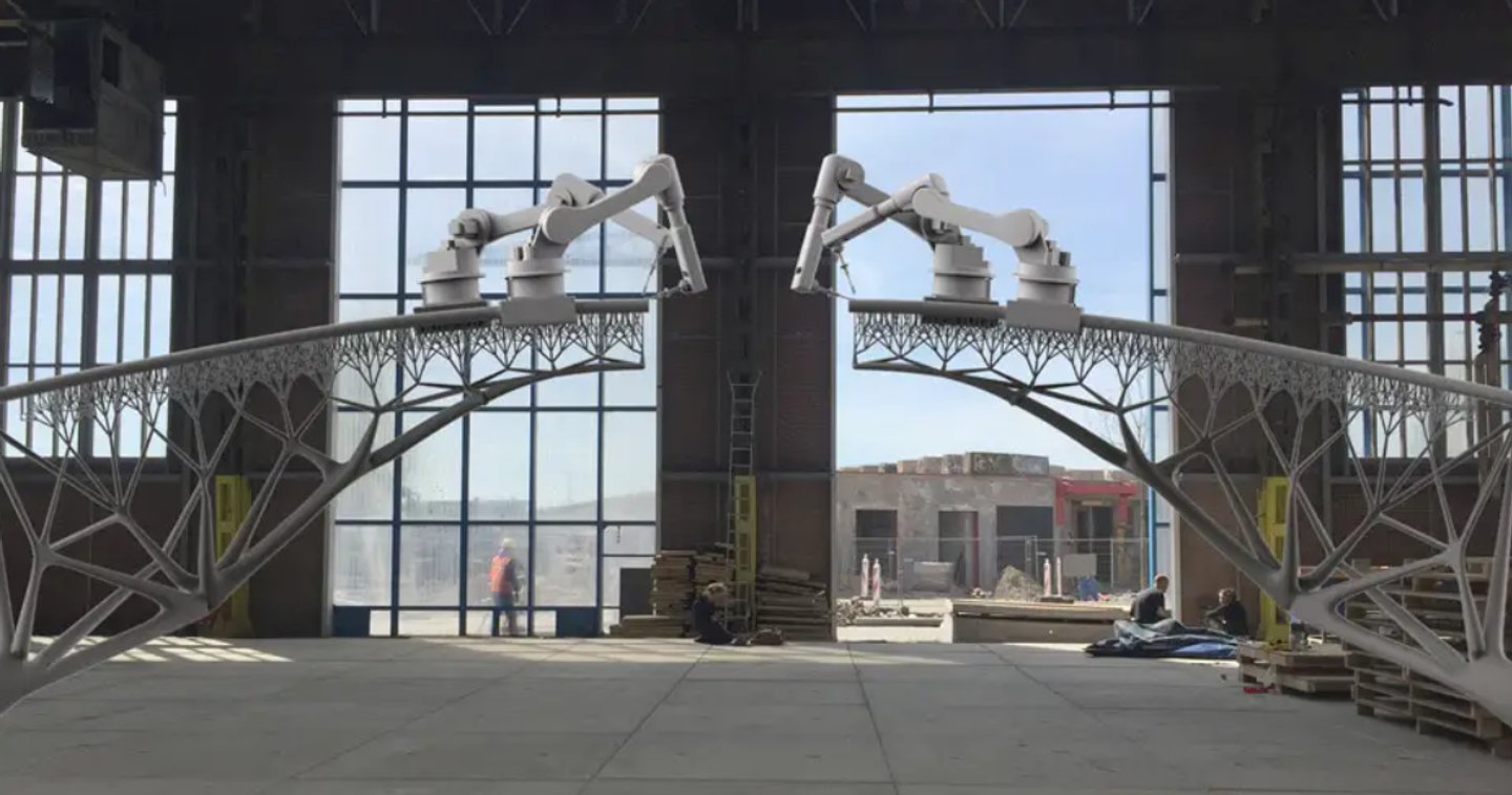
In Medical/Healthcare
Medical sector also is an early adopter of 3D printing. The medical sector was one of the earliest sectors to understand the potential of 3D printing and medical professionals are working with this technology since the early 90’s. By late 90’s and early 2000’s, researchers had already planted a 3D printed organ in a human body. The scientists at the Wake Forest Institute for Regenerative Medicine, 3D-printed the synthetic building blocks of human bladders. This newly generated tissue was then implanted in the human body.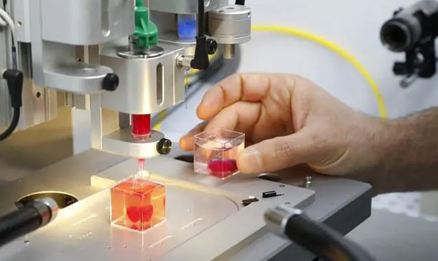
In Automotive
This is another industry where Rapid prototyping is very much essential before actual product manufacturing and implementation. By now, it must be known that Rapid prototyping and 3D printing, almost always, go hand-in-hand. And just like the aerospace industry, automobile industry also welcomed the 3D technology with open arms. Working alongside research teams and incorporating the new technology, 3D products were tested and used in actual applications.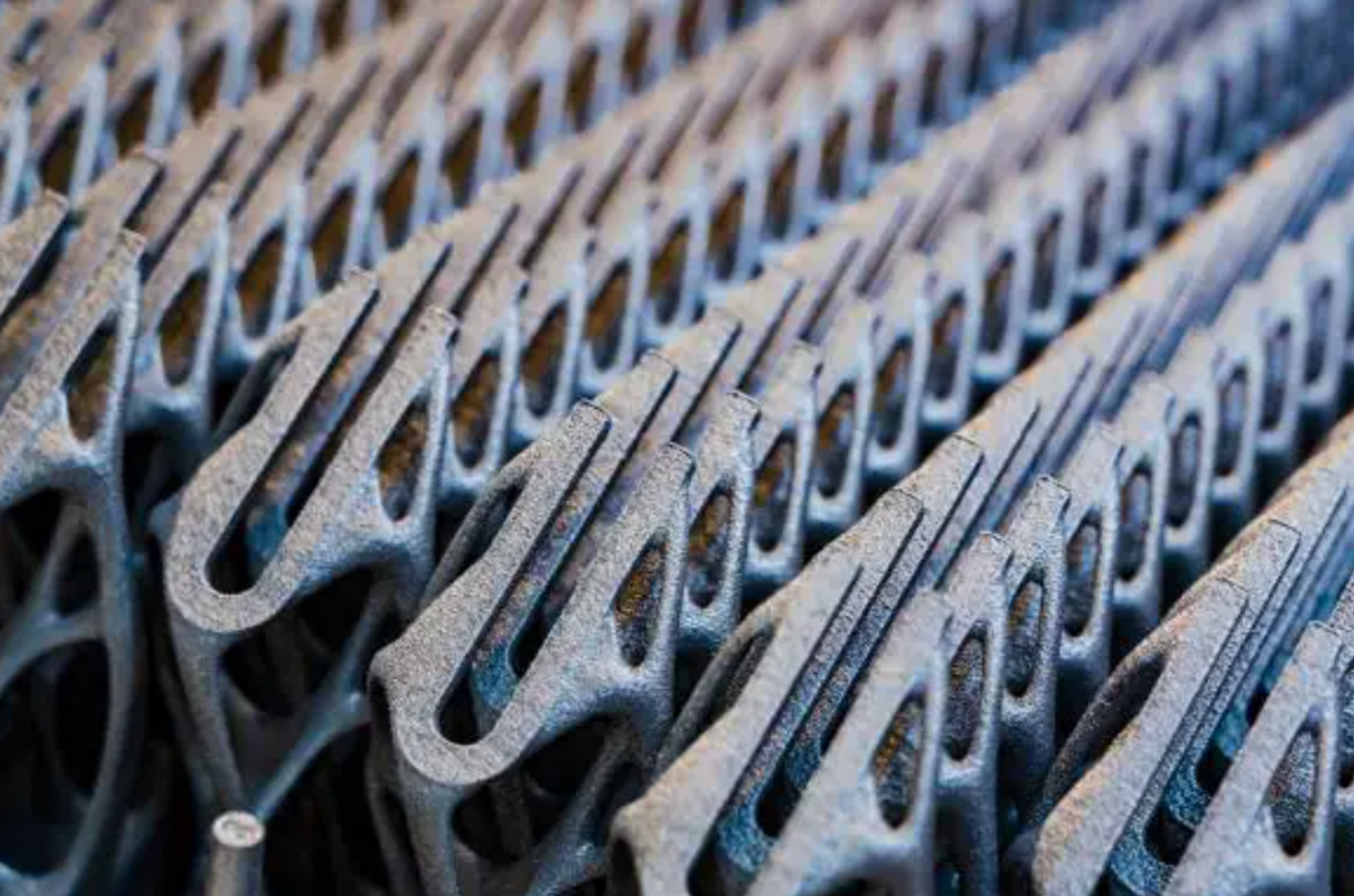
References
Applications of 3D printing - Wikipedia — 3D打印的应用 - 维基百科,自由的百科全书
Applications Of 3D Printing (manufactur3dmag.com)
https://www.thingiverse.com
3D Printer Test
Test model Print with two different parameters
First Printing
- Parameters
| model/ Parameters | nozzle temperature | platform temperature | fill density | base plate |
|---|---|---|---|---|
| model 1 | 200℃ | 30℃ | 15% | Enabled |
(nozzle temperature 200°; platform temperature30℃;fill density 15%; base plate enabled)
3d print software layout the mode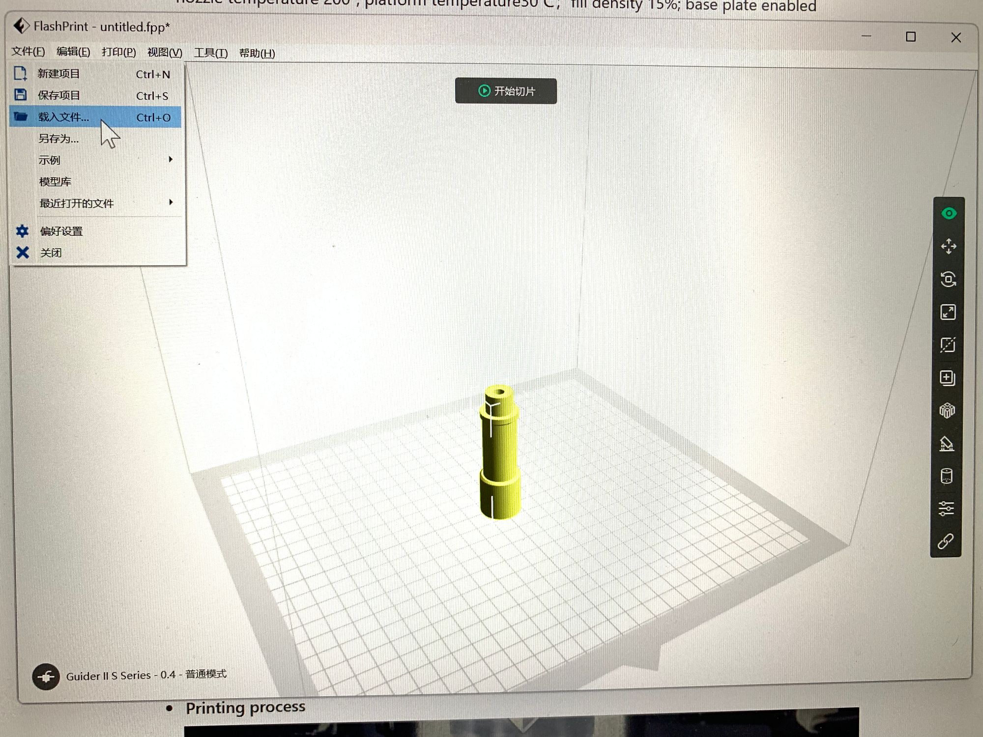
2. Printing process
Tips:When the temperature is too low, it is easy for printing to fail. As shown in the figure below, the print sticks to the print pin.
Advice:Do not lower the temperature below 40° C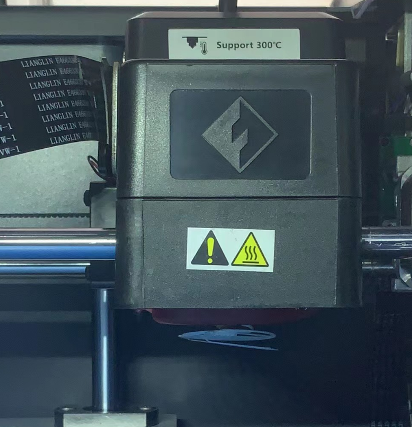
Second printing
1.Parameters
| model/ Parameters | nozzle temperature | platform temperature | fill density | base plate |
|---|---|---|---|---|
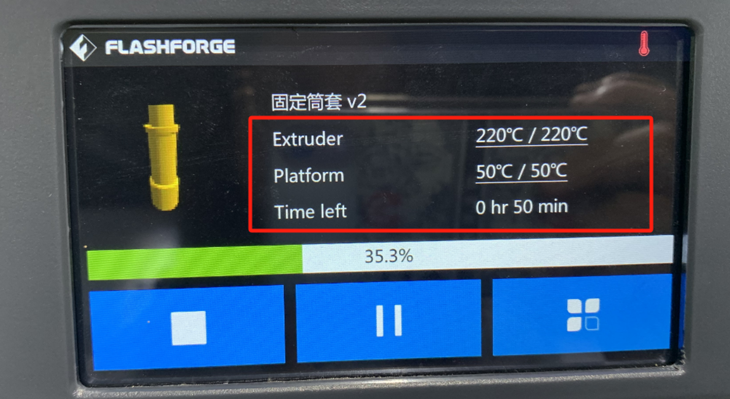
| model 2 | 220℃ | 50℃ | 30% | Disabled |
(nozzle temperature 220°; platform temperature50℃;fill density 30%; base plate disabled)
2.Printing process
Comparison of results between two printouts
1.Parameters Comparison
| model/ Parameters | nozzle temperature | platform temperature | fill density | base plate |
|---|---|---|---|---|
| model 1 | 200℃ | 30℃ | 15% | Enabled |
| model 2 | 220℃ | 50℃ | 30% | Disabled |
- 3D Printing result Comparison
①nozzle/ platform temperature comparison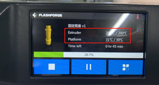
②base plate comparison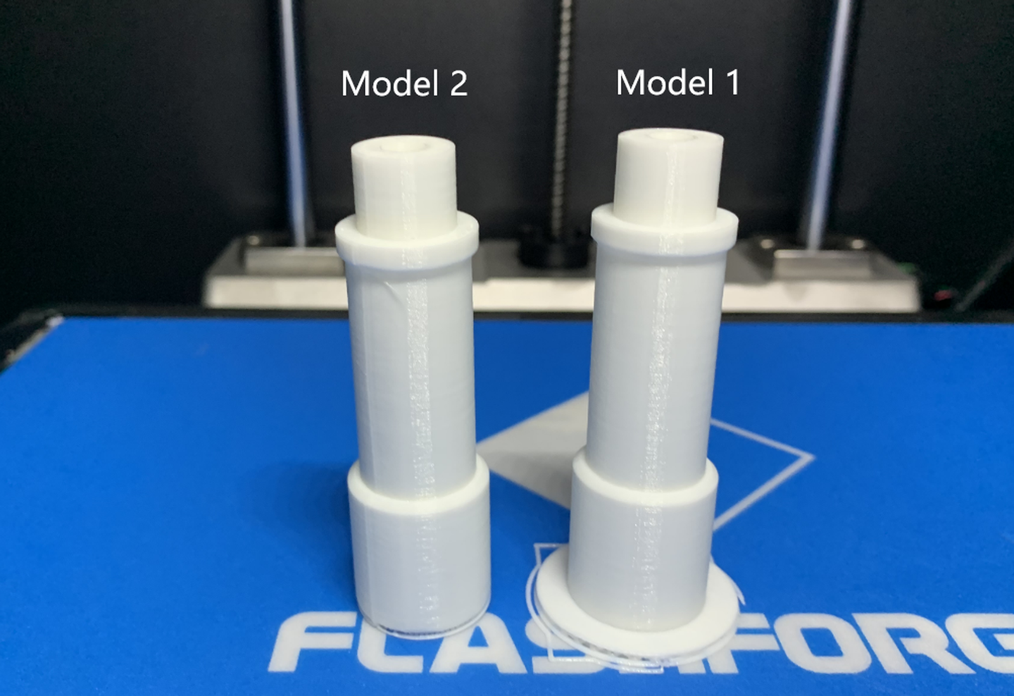
Result: Better quality on the second print
Test the model printing and assemble it
1.The process of 3D printing and laser cutting.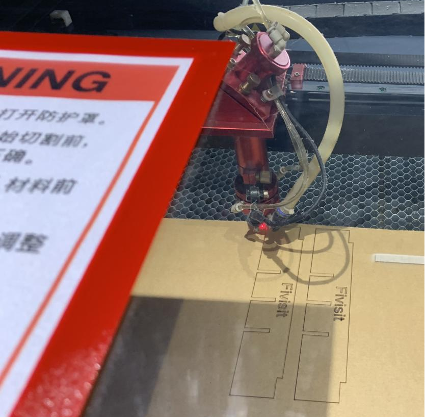
2.Remove the supporting structure of the printed model.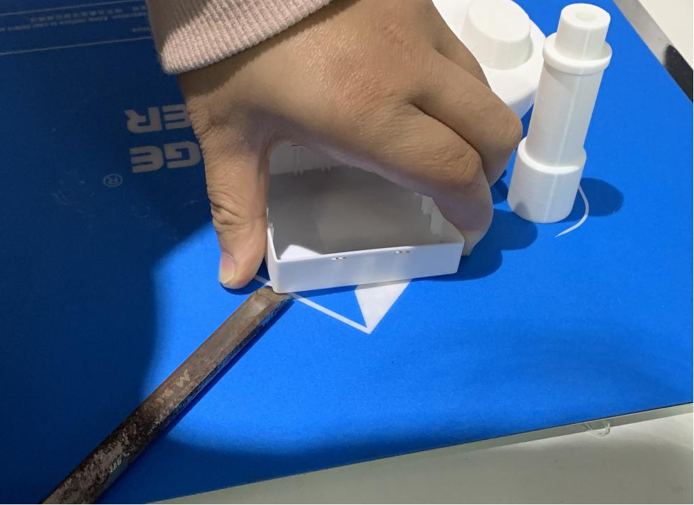
3.Assemble the parts.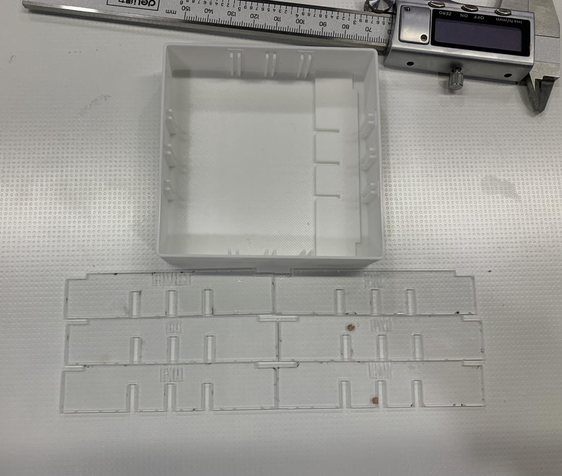
4.The result of the 3D print model.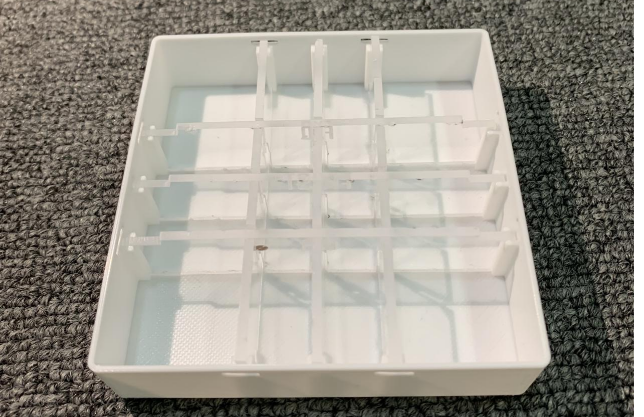
5.Usage scenarios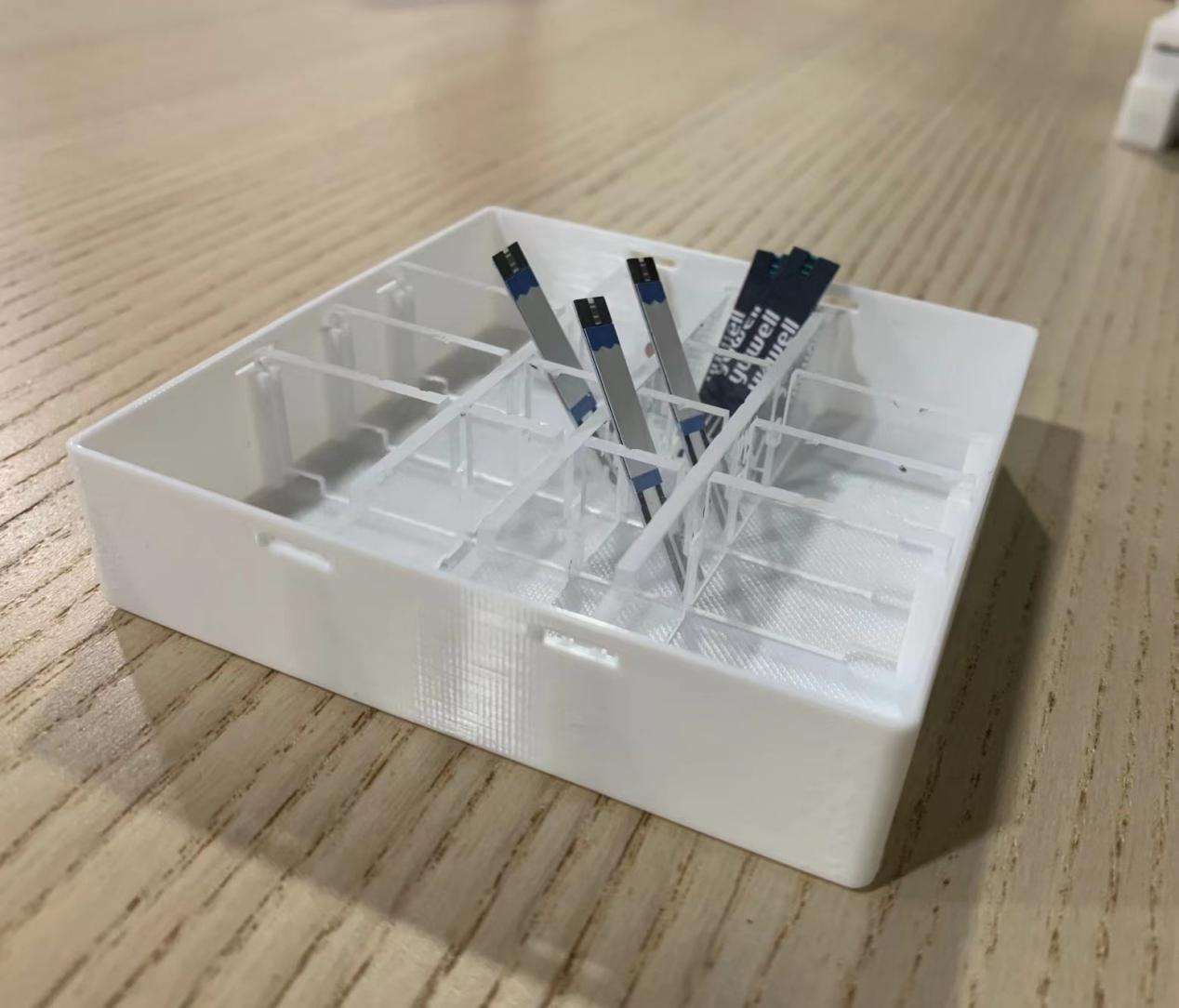
Laser Cutting
Introduction
Types of Laser Cutting
This process can be broken down into three main techniques - CO2 laser (for cutting, boring, and engraving), and neodymium (Nd) and neodymium yttrium-aluminium-garnet (Nd:YAG), which are identical in style, with Nd being used for high energy, low repetition boring and Nd:YAG used for very high-power boring and engraving.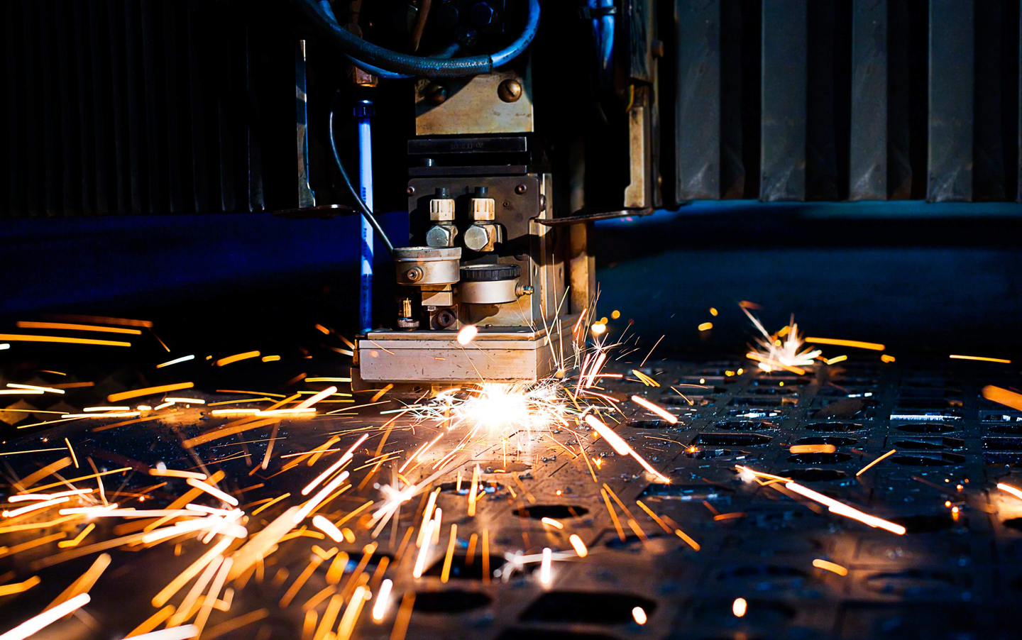
Applications of Lasers in Manufacturing
1. Laser Drilling
Lasers are incredibly accurate at drilling micron-sized holes in a wide range of materials, including metals, polymers, and ceramics.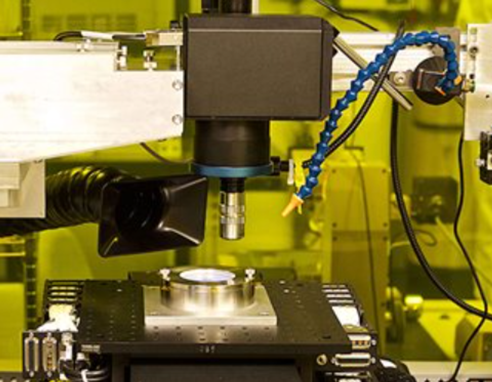
2.Surface Texturing
Lasers can create textures or patterned microstructures on the surfaces of components or products that improve physical performance, such as wear rates, grip, optical properties, and load capacity. Laser micro-texturing can create roughness on medical implants that make it easier for new tissue or bone to take hold and grow into the new implant, and patterns with features as small as 10 µm can be produced with very high depth resolution.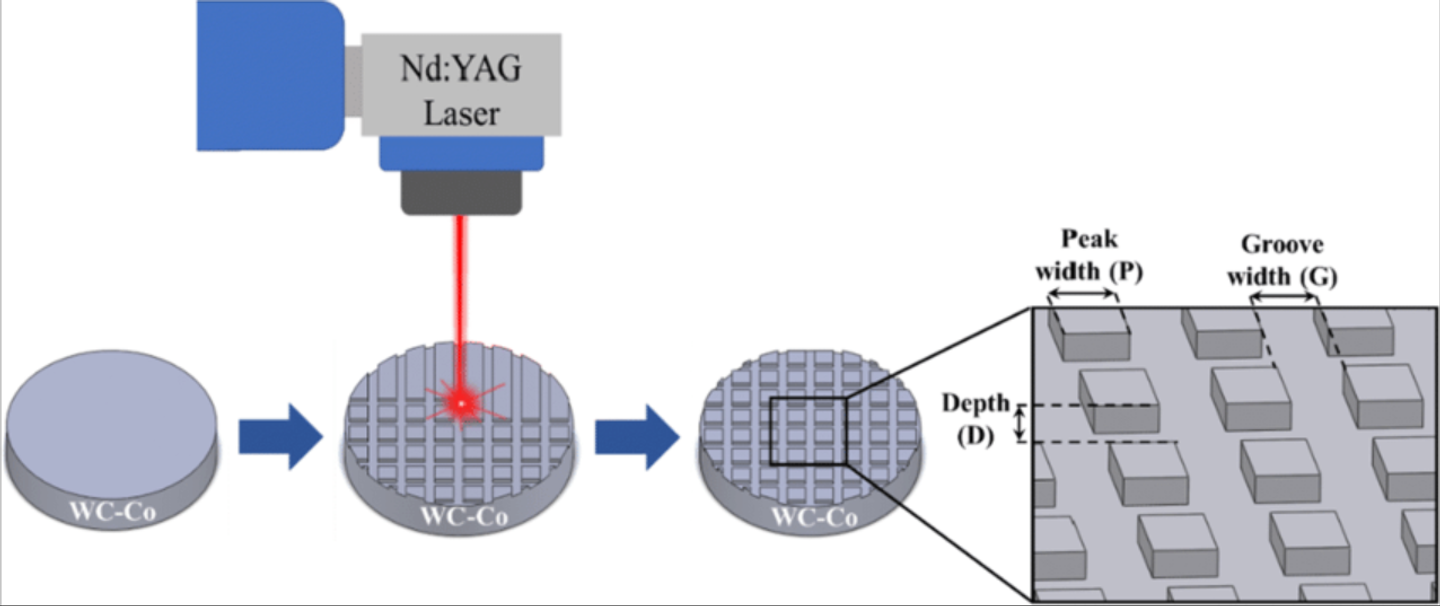
References
laser24.co.uk
Laser Scabbling - TWI (twi-global.com)
Power and Speed Test
1.The software sets the power and speed of the test pattern hierarchically.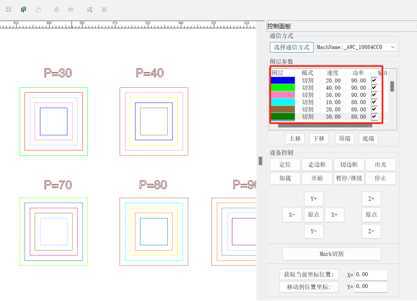
2.Cutting test with machine.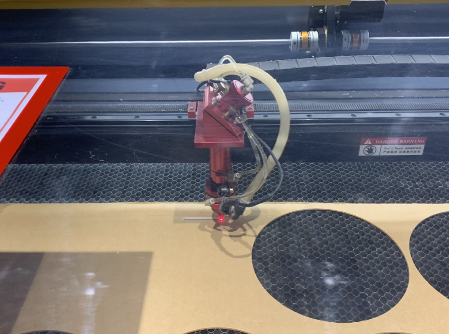
3.The two results of the laser cutting.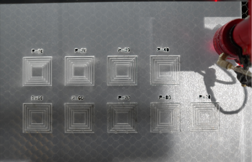
4.Statistics on cutting test results.
| 速度/功率 | 10 | 20 | 30 | 40 | 50 | 60 | 70 |
|---|---|---|---|---|---|---|---|
| 10 | × | √ | √ | √ | √ | √ | √ |
| 20 | × | × | √ | √ | √ | √ | √ |
| 30 | × | × | √ | √ | √ | √ | √ |
| 40 | × | × | × | √ | √ | √ | √ |
| 50 | × | × | × | × | × | √ | √ |
Cutting Accuracy Test
1.Import cutting target image to the machine.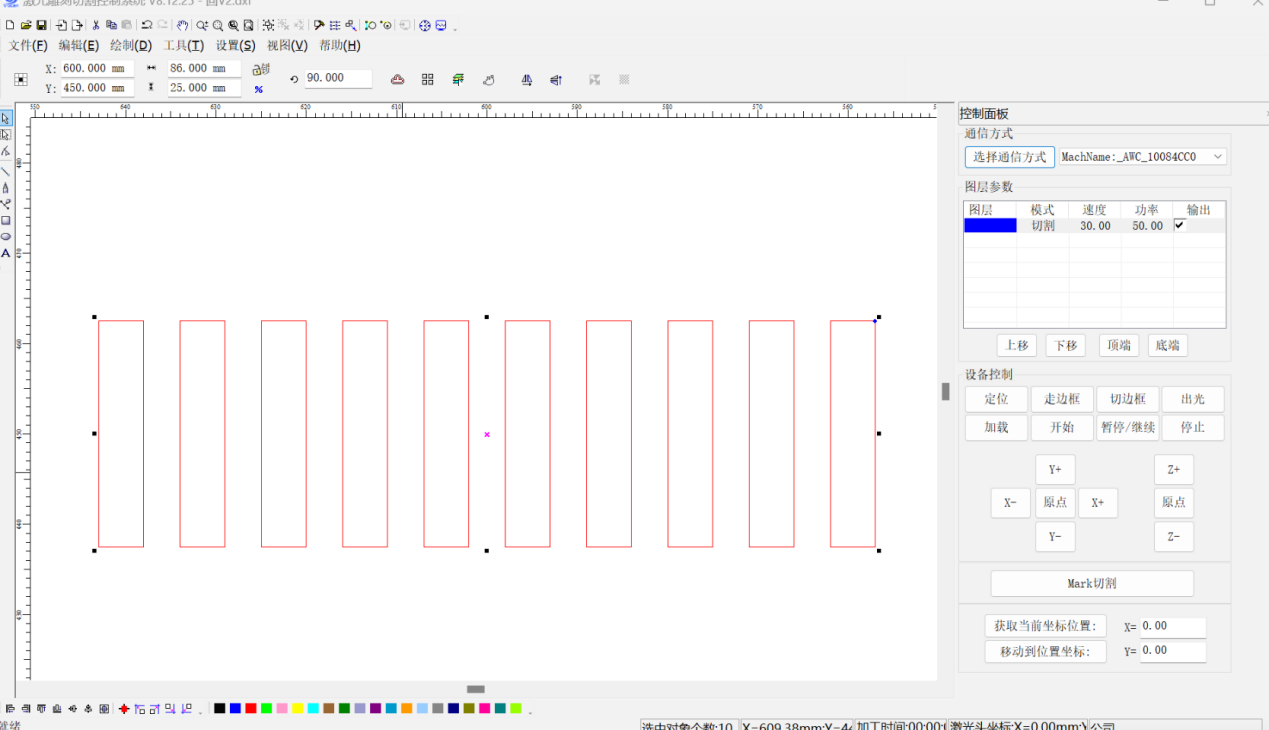
2.Measure the actual length to see the error. The width of a single part is 5mm, the number is 10, the total statistical length is 46.96mm, and the error is 3.04mm. Therefore, the value of Kurf is 3.04/10=0.304mm.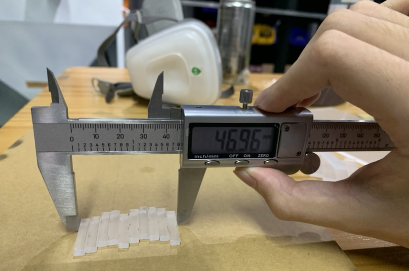
Laser Cutting Practice
Preparation
1.open fume extractor before run the machine
2.Turn on the master switch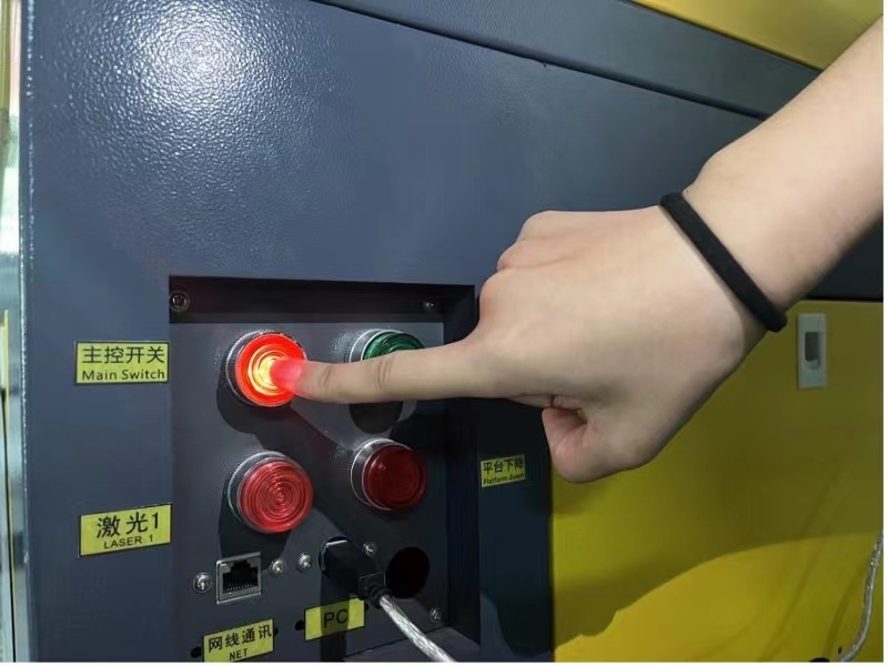
3.Turn on the laser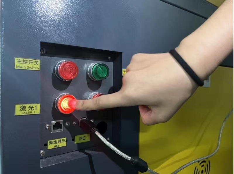
4.Access computer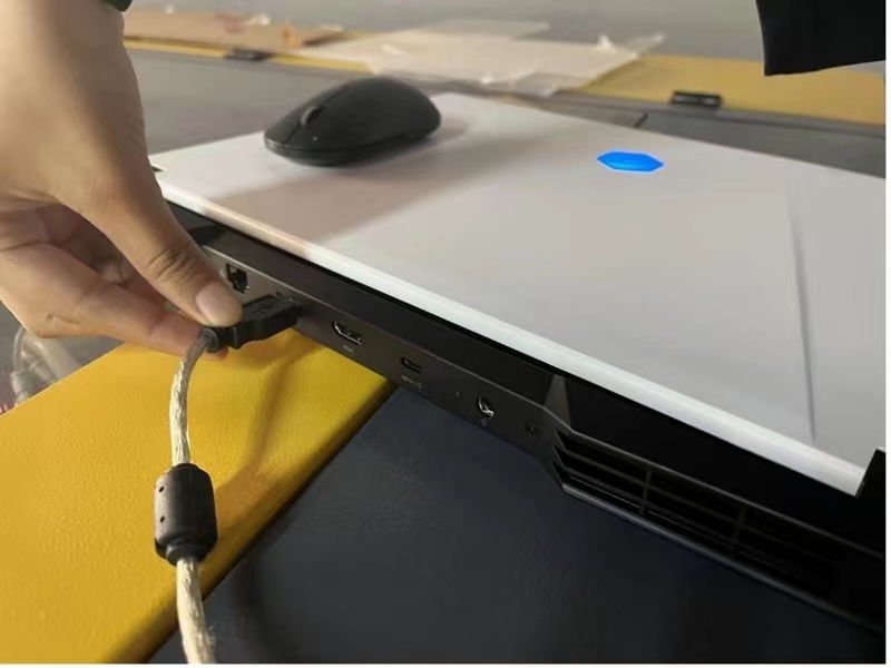
5.Open the lid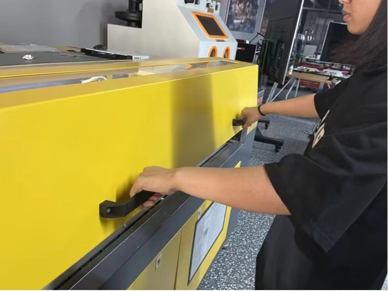
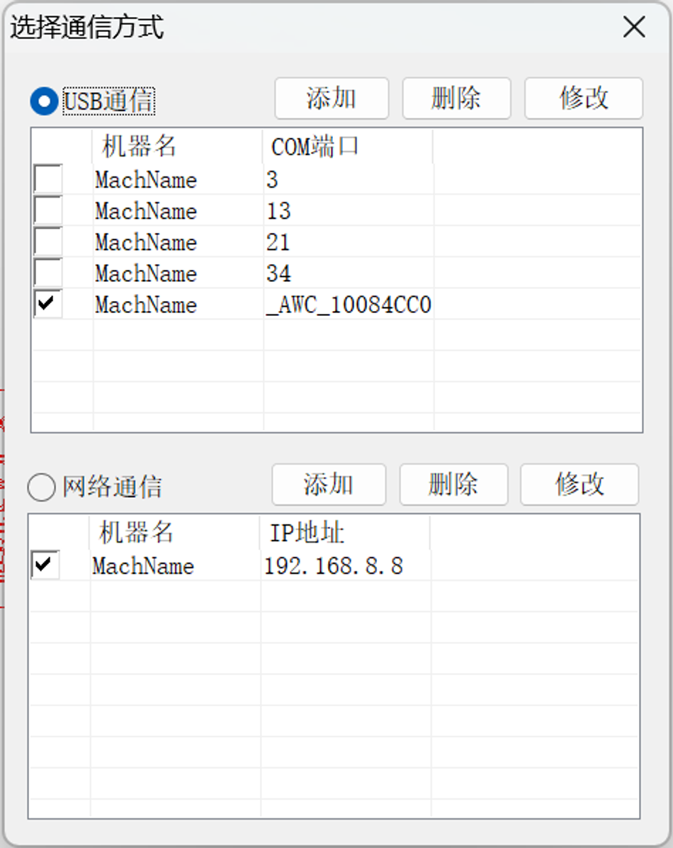
6.Transport data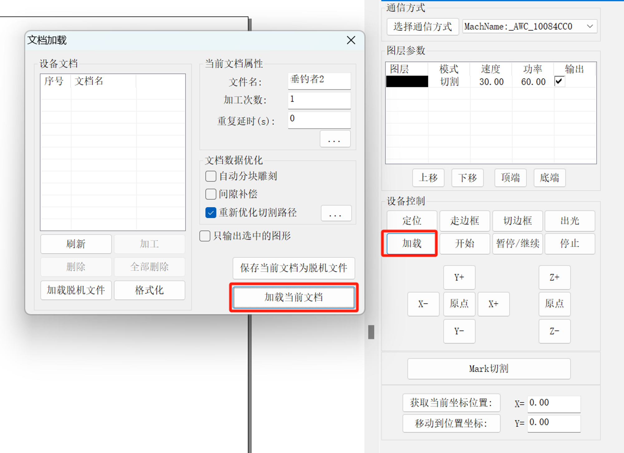
7.Moving Laser Position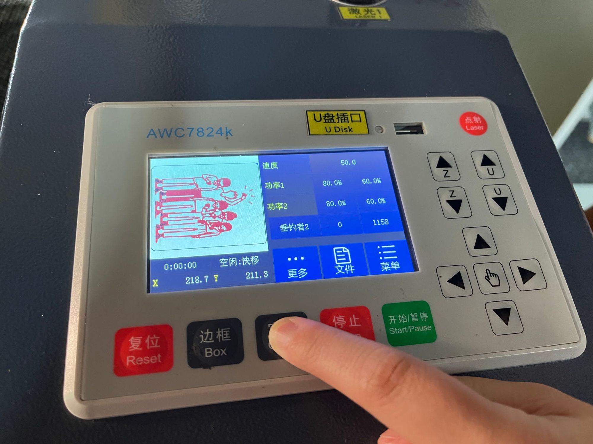
8.Mobile platforms for positioning 1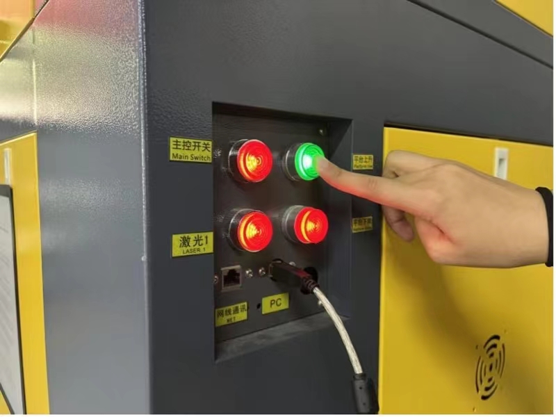
9.Mobile platforms for positioning 2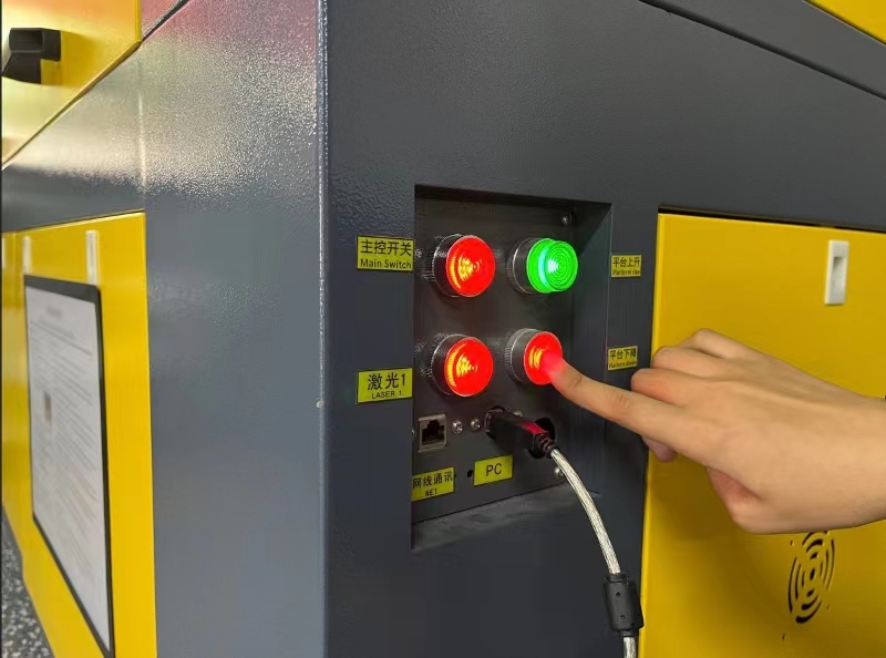
Laser cutting practice—using wooden to cutting
1.Draw the shape with Adobe Illustrator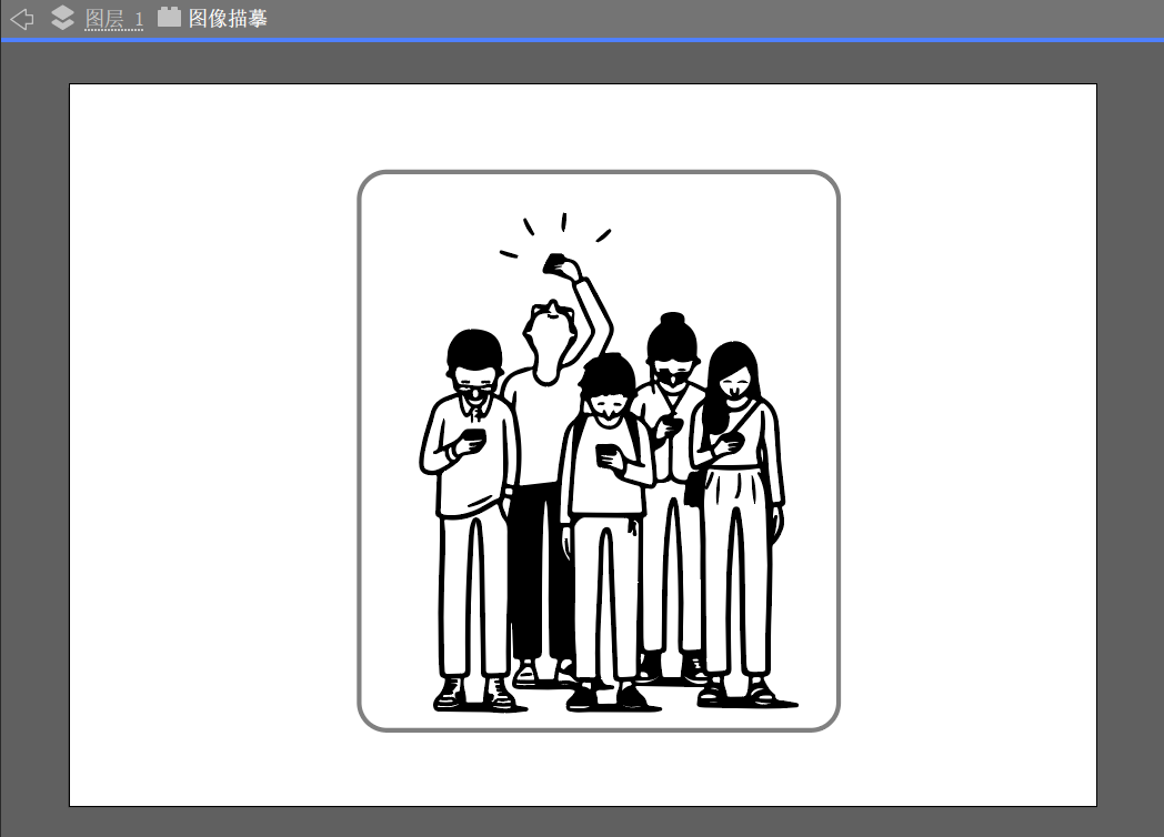
2.Import the file into Laser CAD V8.12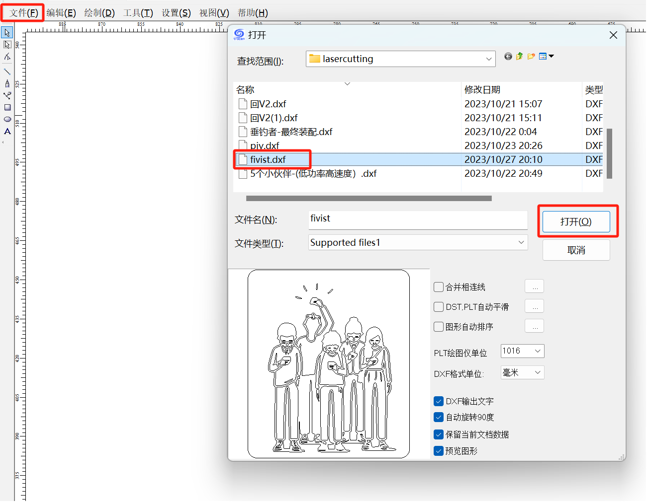
3.Set different parameters (power/speed) with different colors in Laser CAD V8.12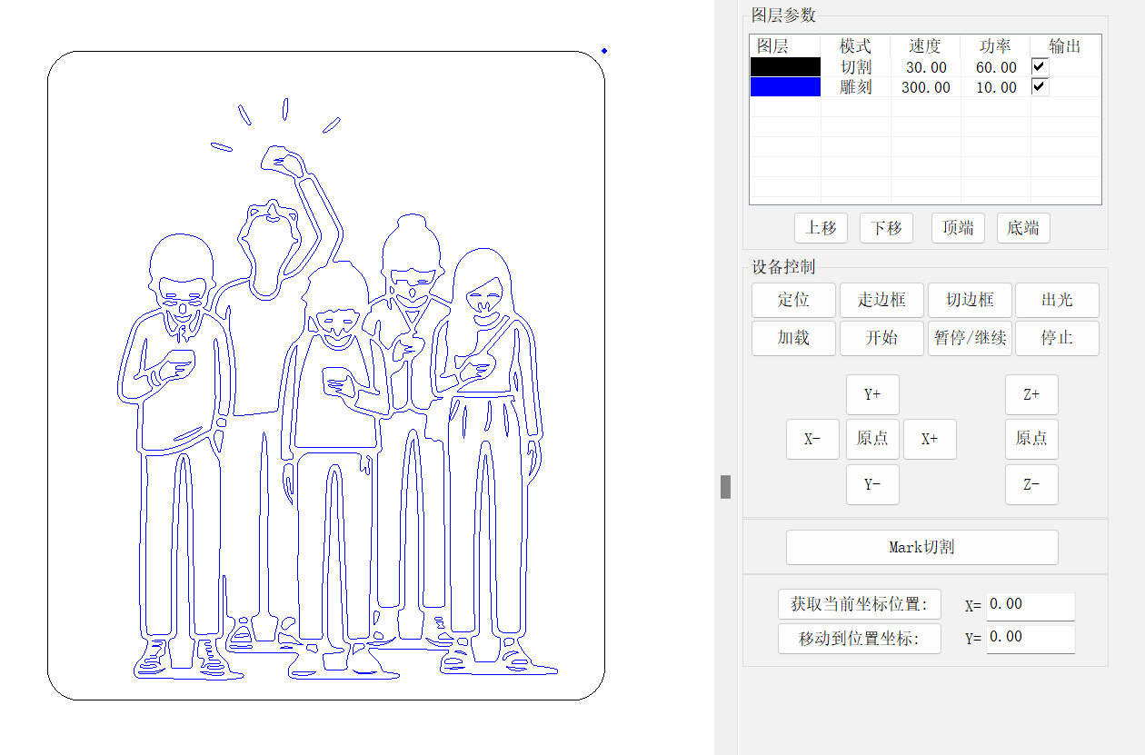
4.Open the Laser cutting machine to location and border running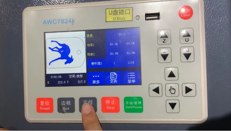
5.Begin to laser cutting
6.The result of laser cutting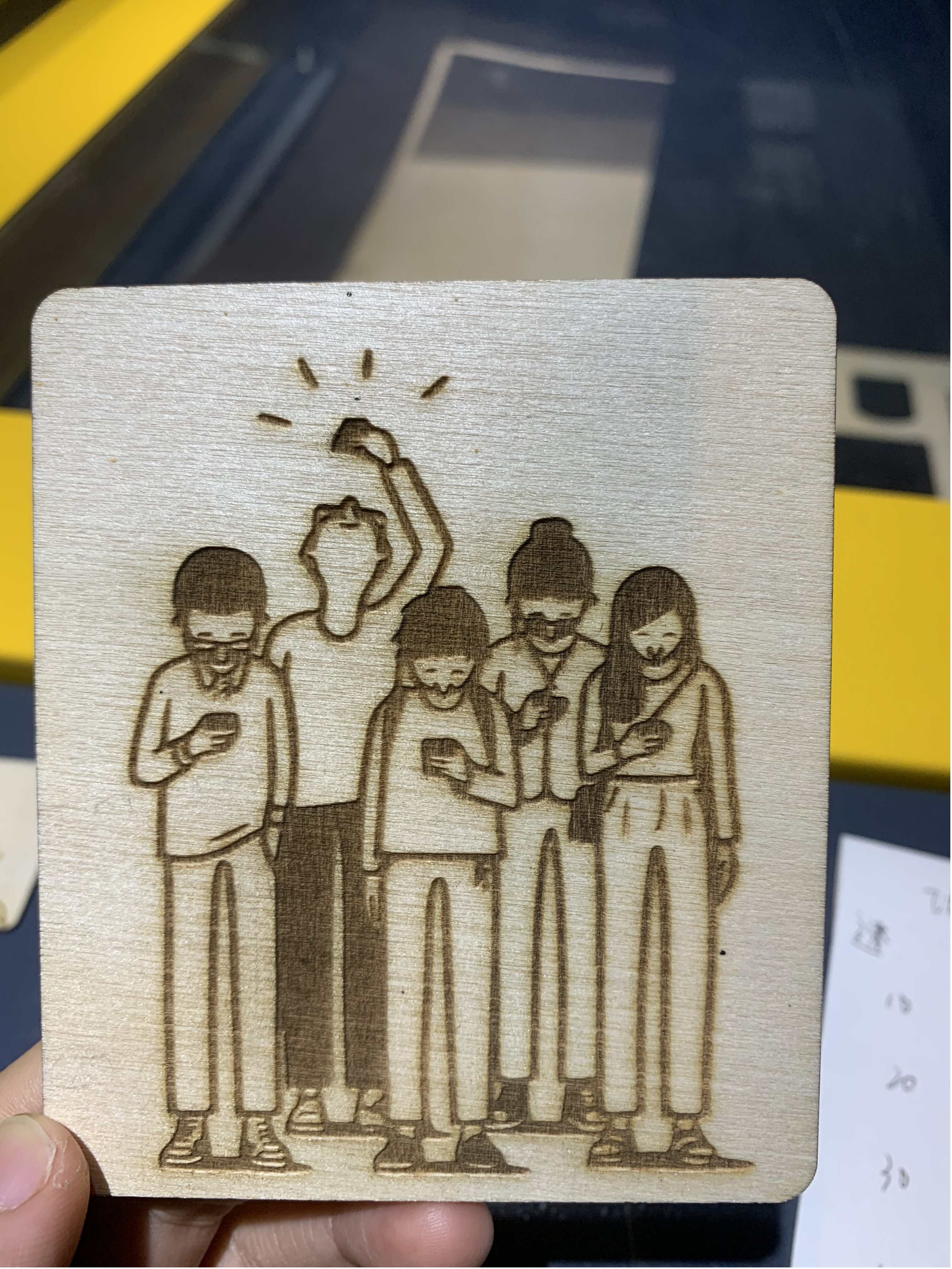
Assemble with arduino project
Process
- Use laser cutting to cut Nylon TPU
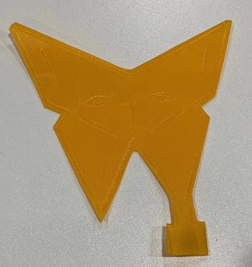
2.Use arduino with pump to control the motion of the soft robot.
Code
1 | #include <FastLED.h> |
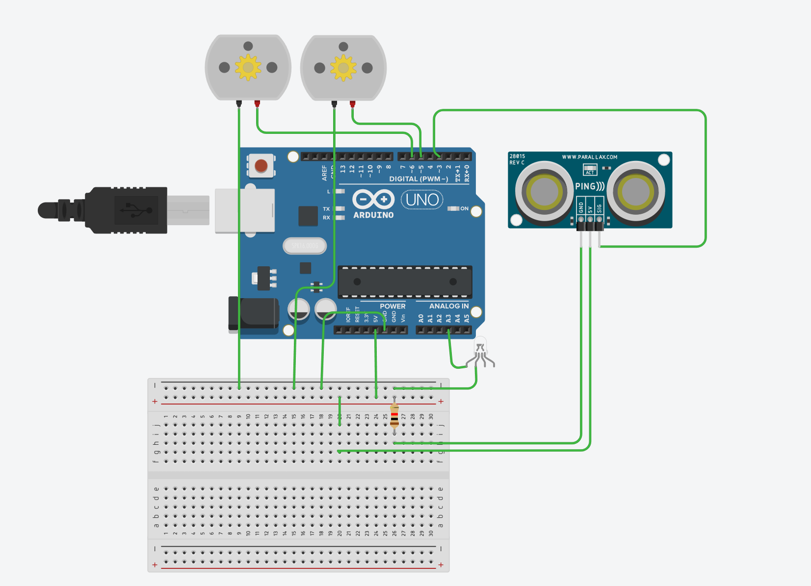
Tinkcad Diagram