Introduction
Fusion 360 is a 3D modeling software from Autodesk that integrates industrial design, mechanical design, and digital machining, and is also the world’s first cloud-based collaborative CAD, CAE, CAM, and Project Management product creation platform. We use the Fusion 360 platform to build a three-jaw inside micrometer, the sectional view and the final model are shown below.
Modeling Showcase
Fixed sleeve
Differential barrel
Measuring claw
Shaft section
Conical pin
Modeling Procedure
1. Basic parameter design
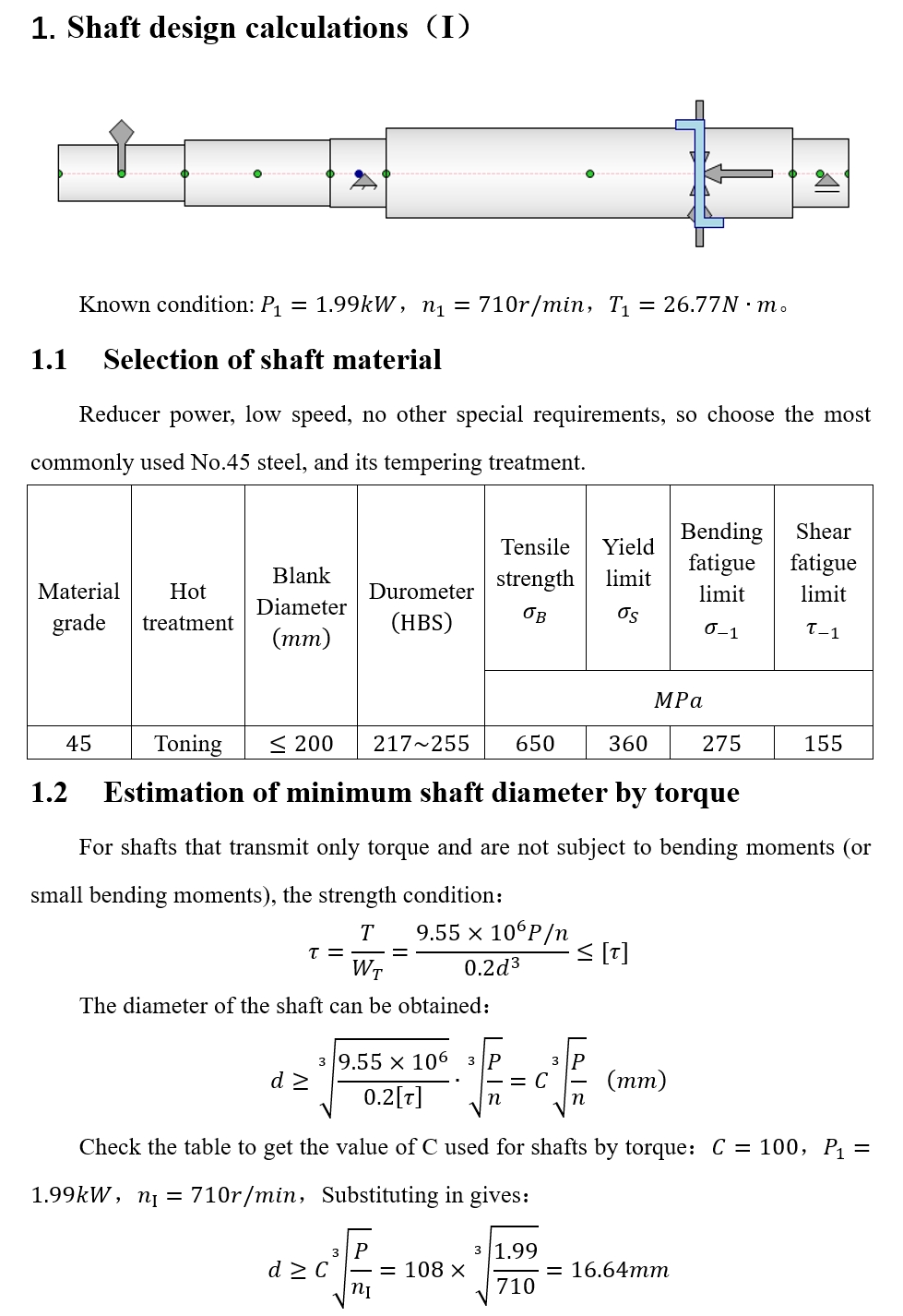
The main process of parametric design of the shaft is as follows
·Determine key data such as output power, speed and torque of the shaft according to the performance requirements of the gearbox.
·Select the shaft material and determine the minimum shaft diameter according to the torque requirement.
·Select angular contact bearings from the minimum shaft diameter, and determine the diameters and lengths of the shaft segments according to the standard parametric design requirements.
·latexlive can convert formulas to LaTeX format code for publication on the website.
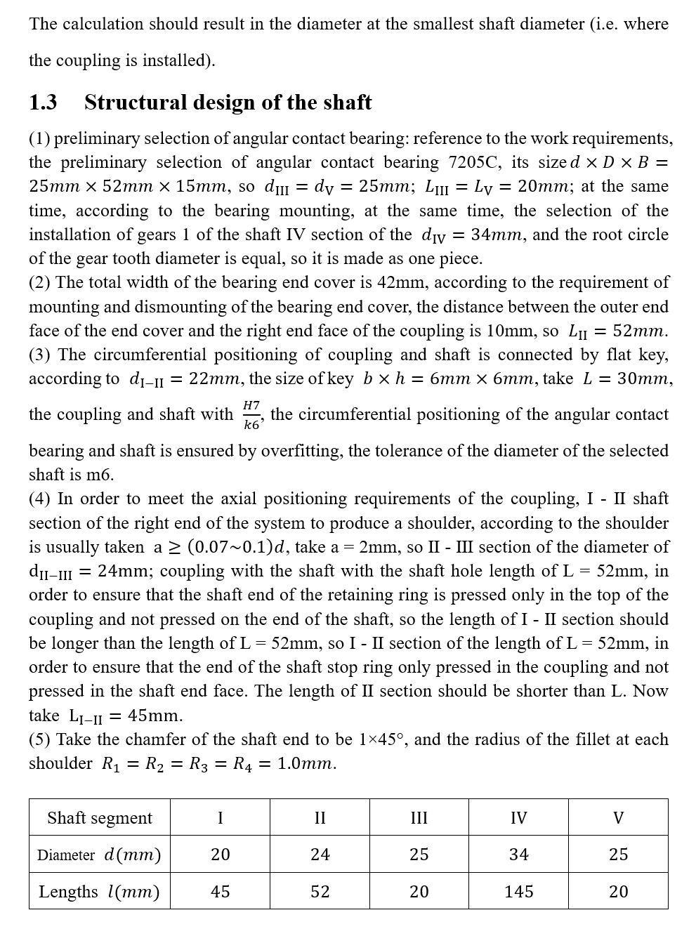
2. New Component
Detailed modeling of this part is demonstrated:
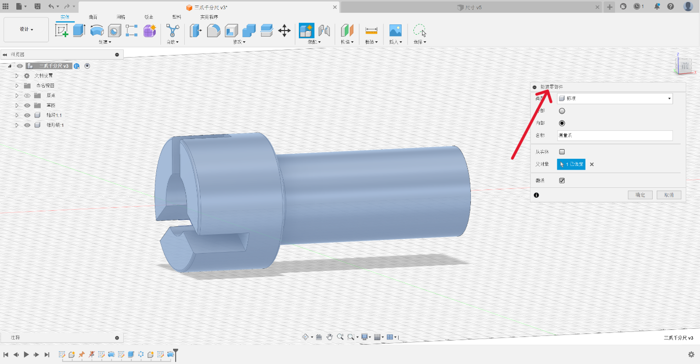
3. Draw a sketch
Draw a sketch of the measuring claw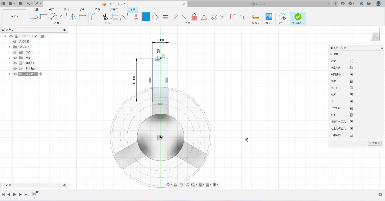
4. Create a measurement entity
Create a measurement claw entity using the ‘Stretch’ command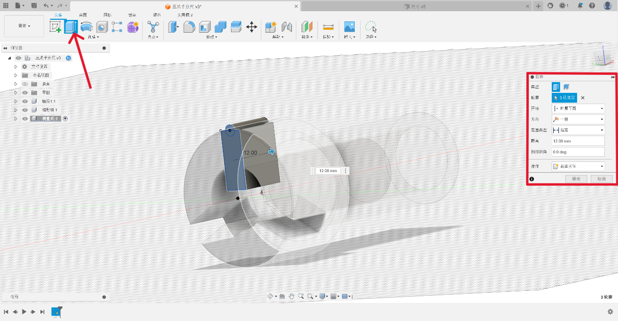
5. obtain the specified number
By using the “Circular Array” command, select the required number of components to obtain the specified number and corresponding angle of copied components. Each component maintains synchronization with the modification command.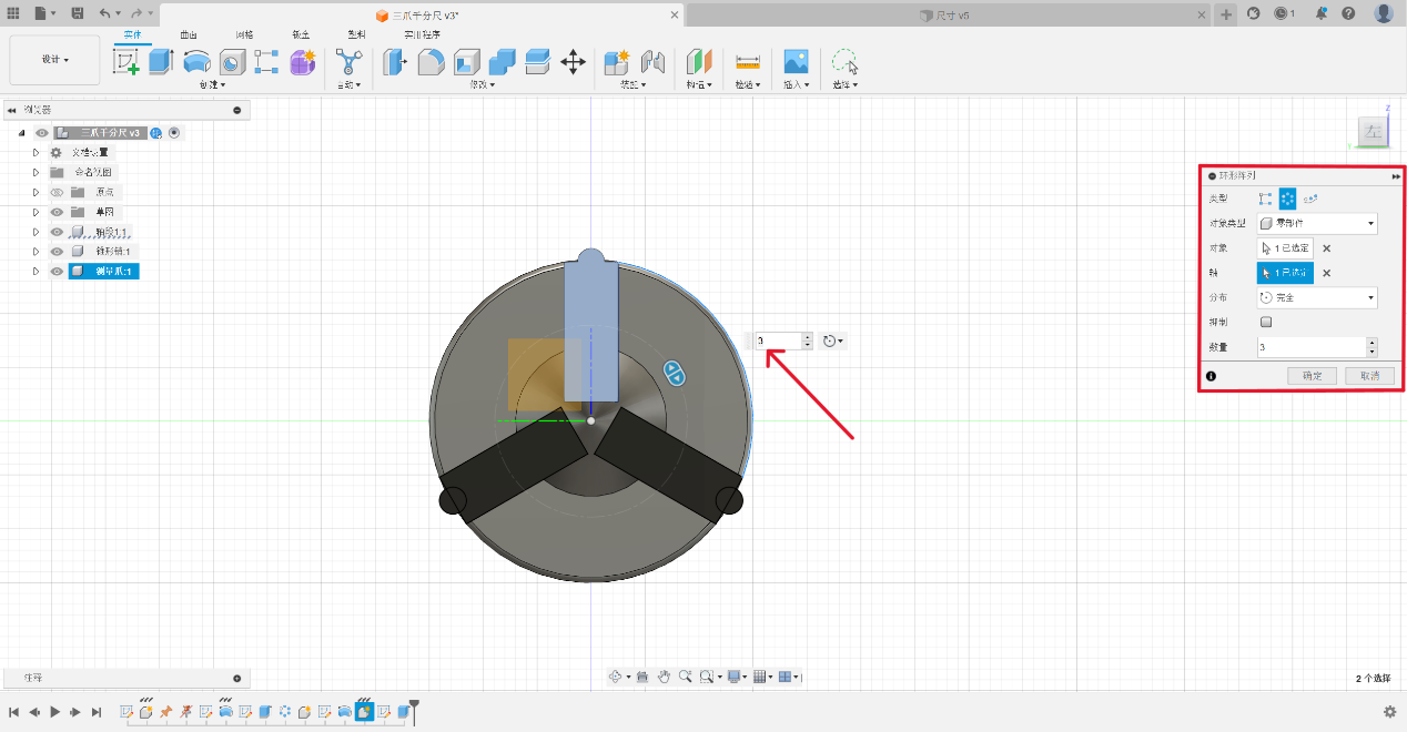
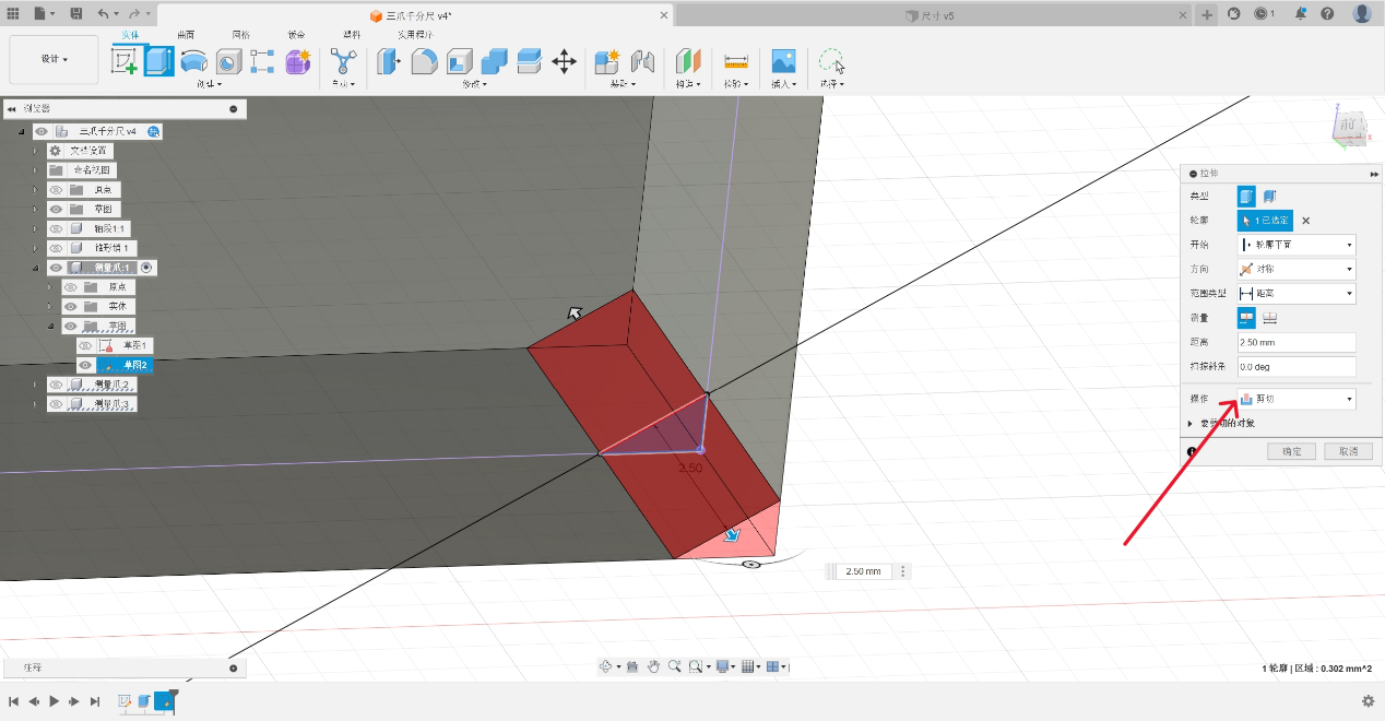
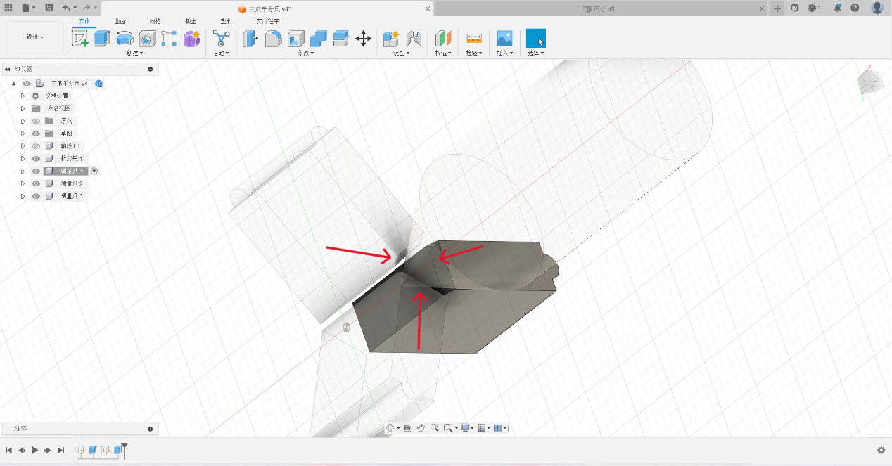
6. fit the tapered pin
Cut the measuring claw through the “Stretch” and “Cut” commands to make it fit with the tapered pin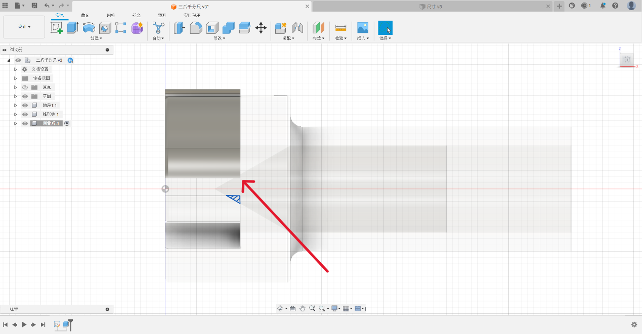
It can be seen that the three components established by the “circular pattern” command execute modification commands synchronously.
7. Create a connection
Create a “slider” connection between specified components using the “Link” command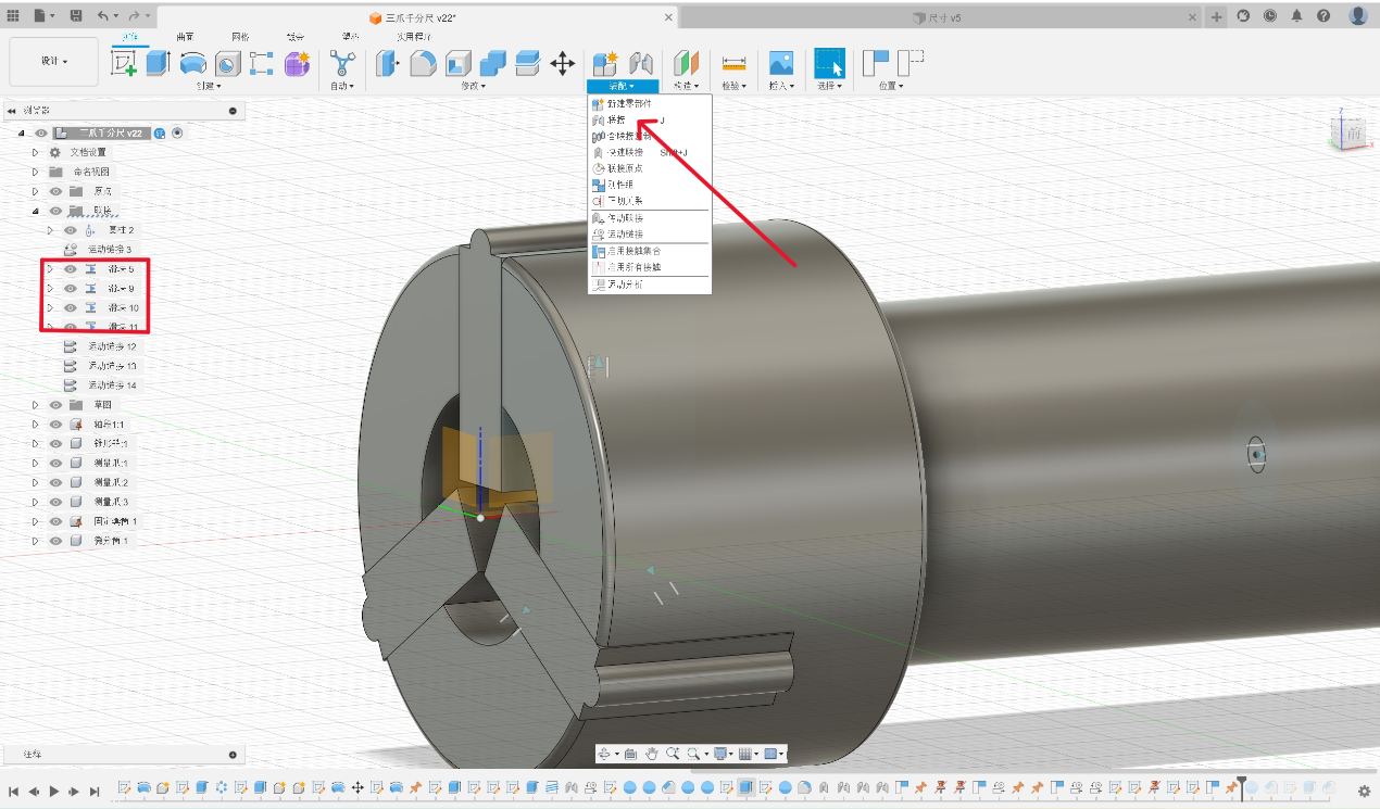
8. establish a motion distance ratio
By using the “Motion Link” command, establish a motion distance ratio between two specified “connections”. In this example, the ratio of the motion distance between the conical pin and the measuring claw is 1:0.577 (1: tan30 °)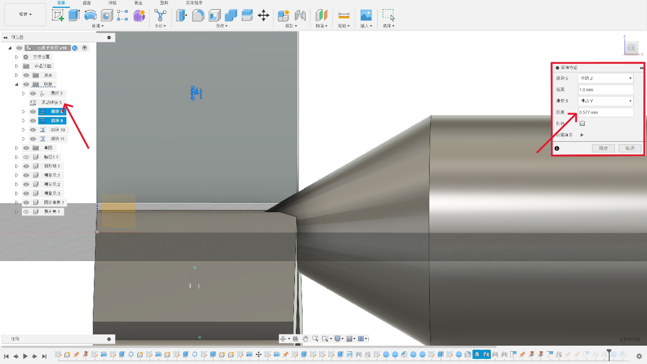
9. establish a cylindrical connection
By using the “Connect” command, establish a “cylindrical connection” between the fixed sleeve and the differential cylinder. Due to the pitch of the micrometer screw being 0.5mm, the micrometer screw moves forward or backward 0.5mm when the differential cylinder rotates once. Therefore, set the distance between the micrometer screws in the cylindrical connection to 0.5mm.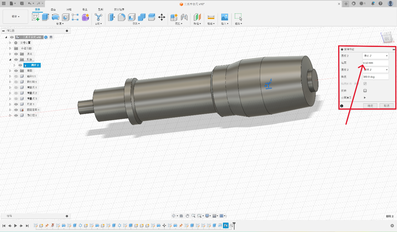
Motion Animation
Motion animation process:
Motion animation demonstration:
The Plugin of the Fusion360
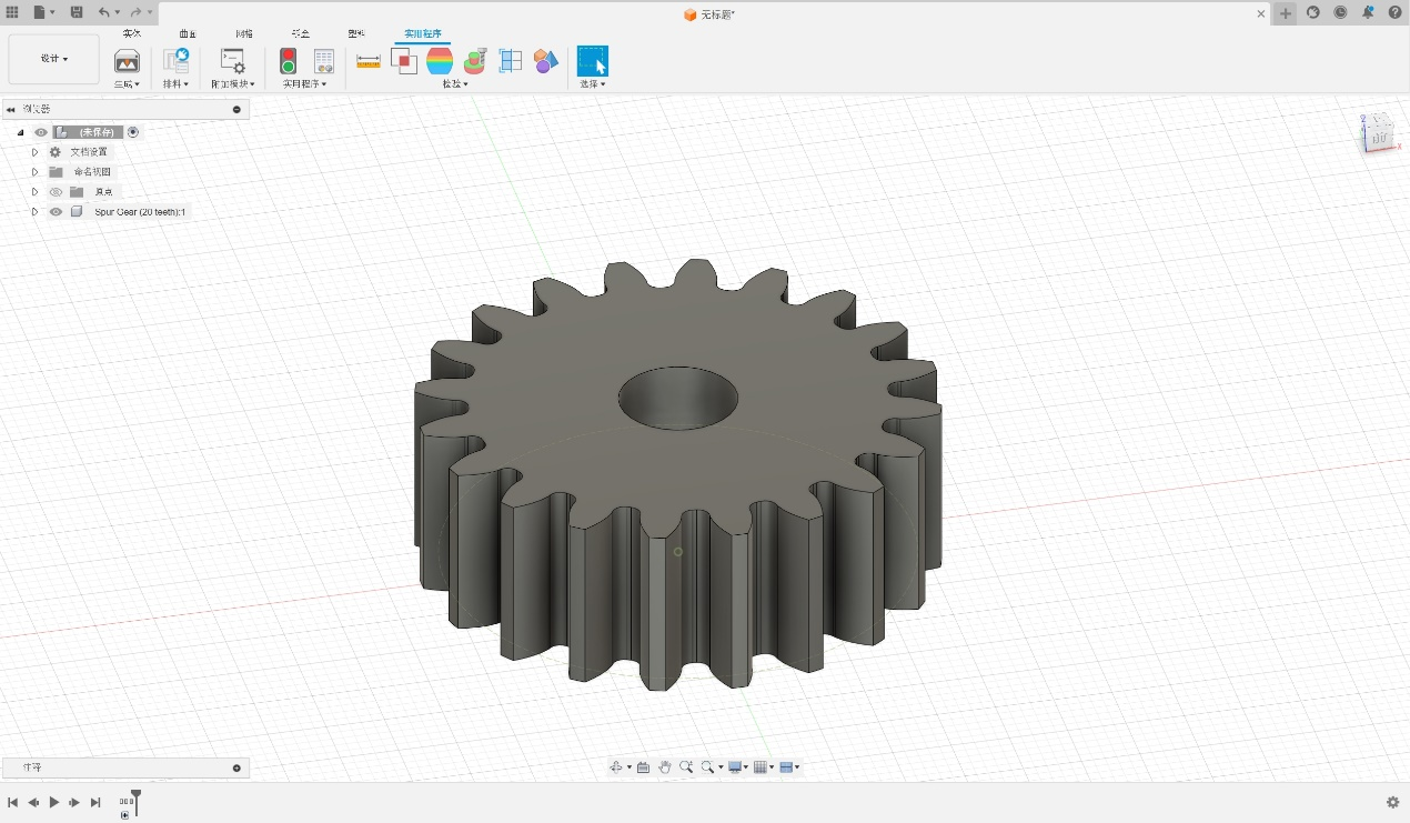
- Click the plugin button and choose the SpurGear as the plugin.
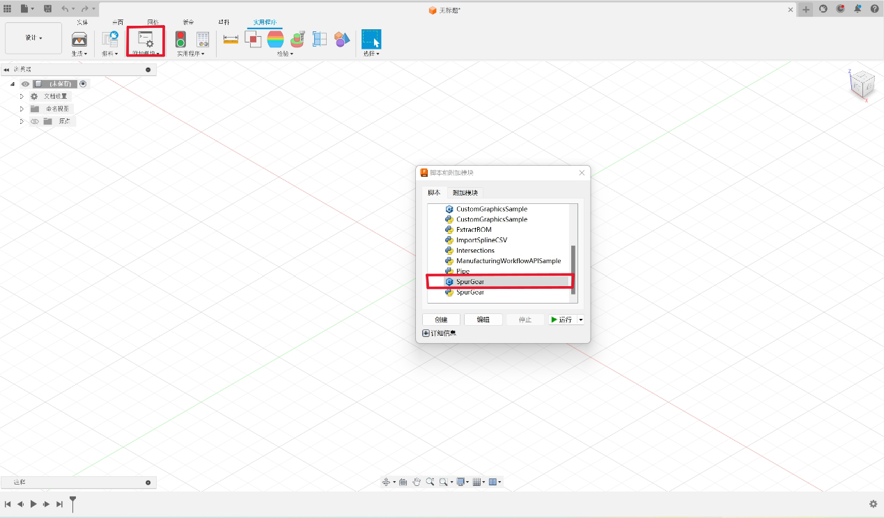
- Adjust the parameter of the plugin to make a gear.
Data are as follows:
Pressure Angle = 20°
Module = 2
Number of Teeth = 20
Root Fillet Radius = 1mm
Gear Thickness = 15mm
Hole Diameter = 10mm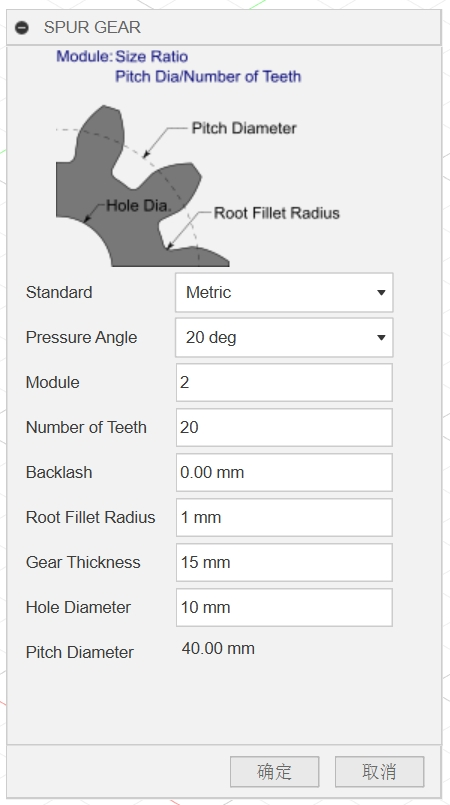
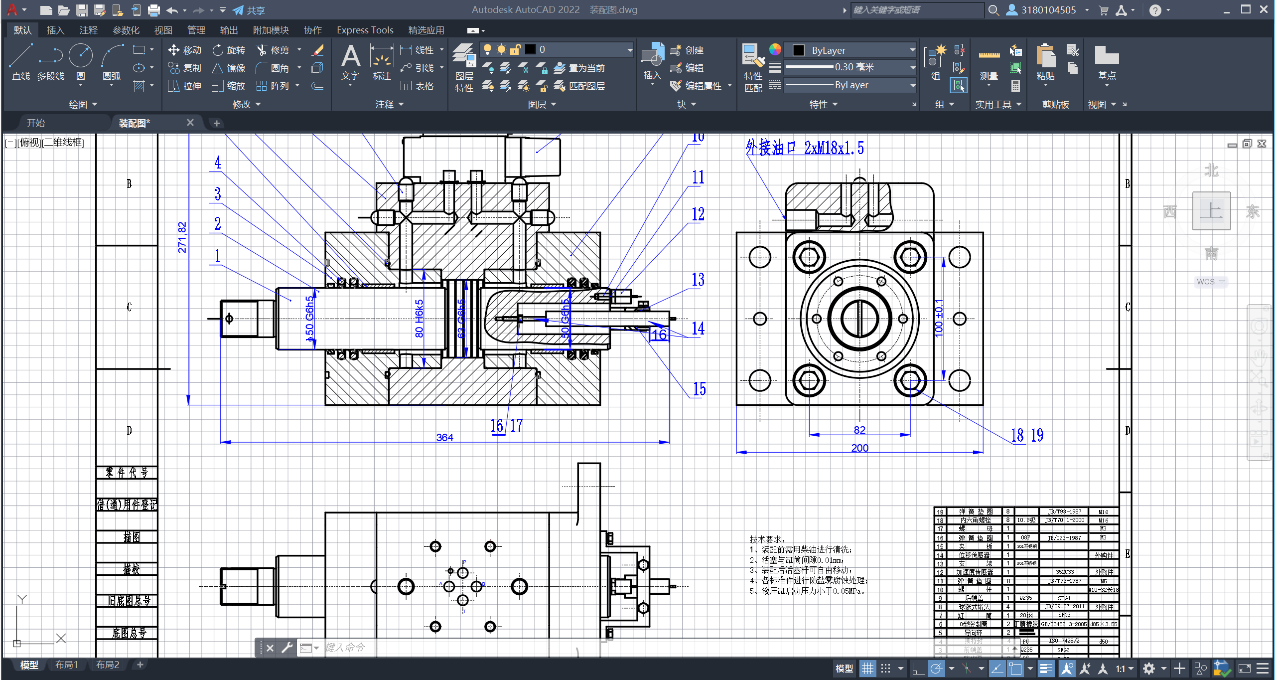
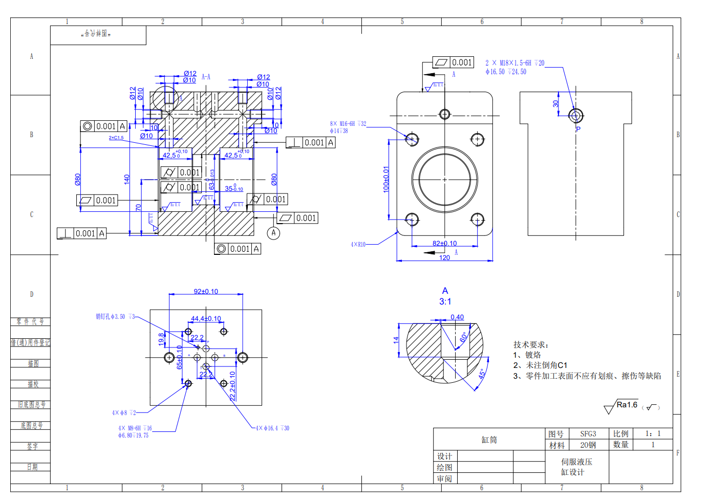
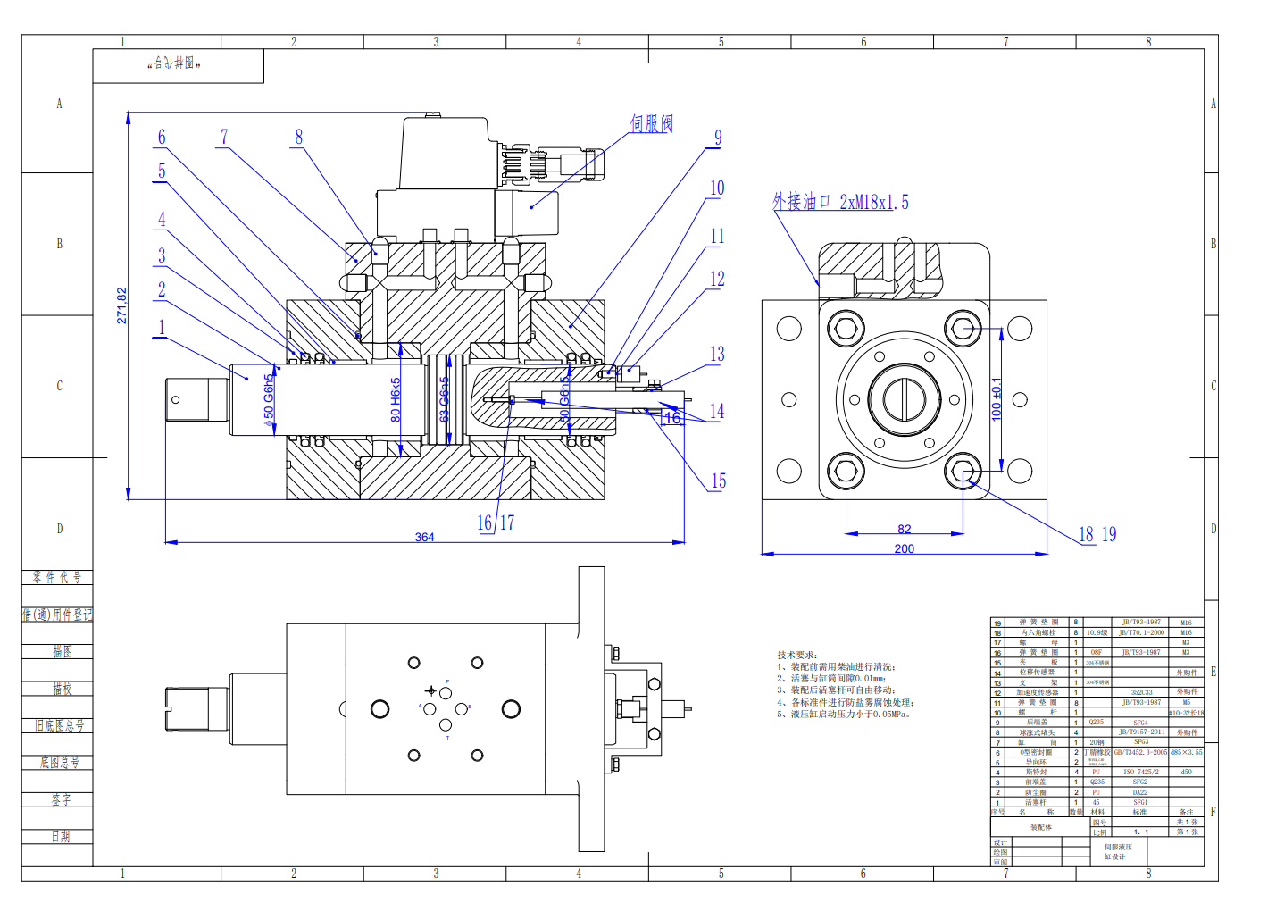
Mechanical Drawing
In Autodesk Fusion360, generate mechanical drawing through model.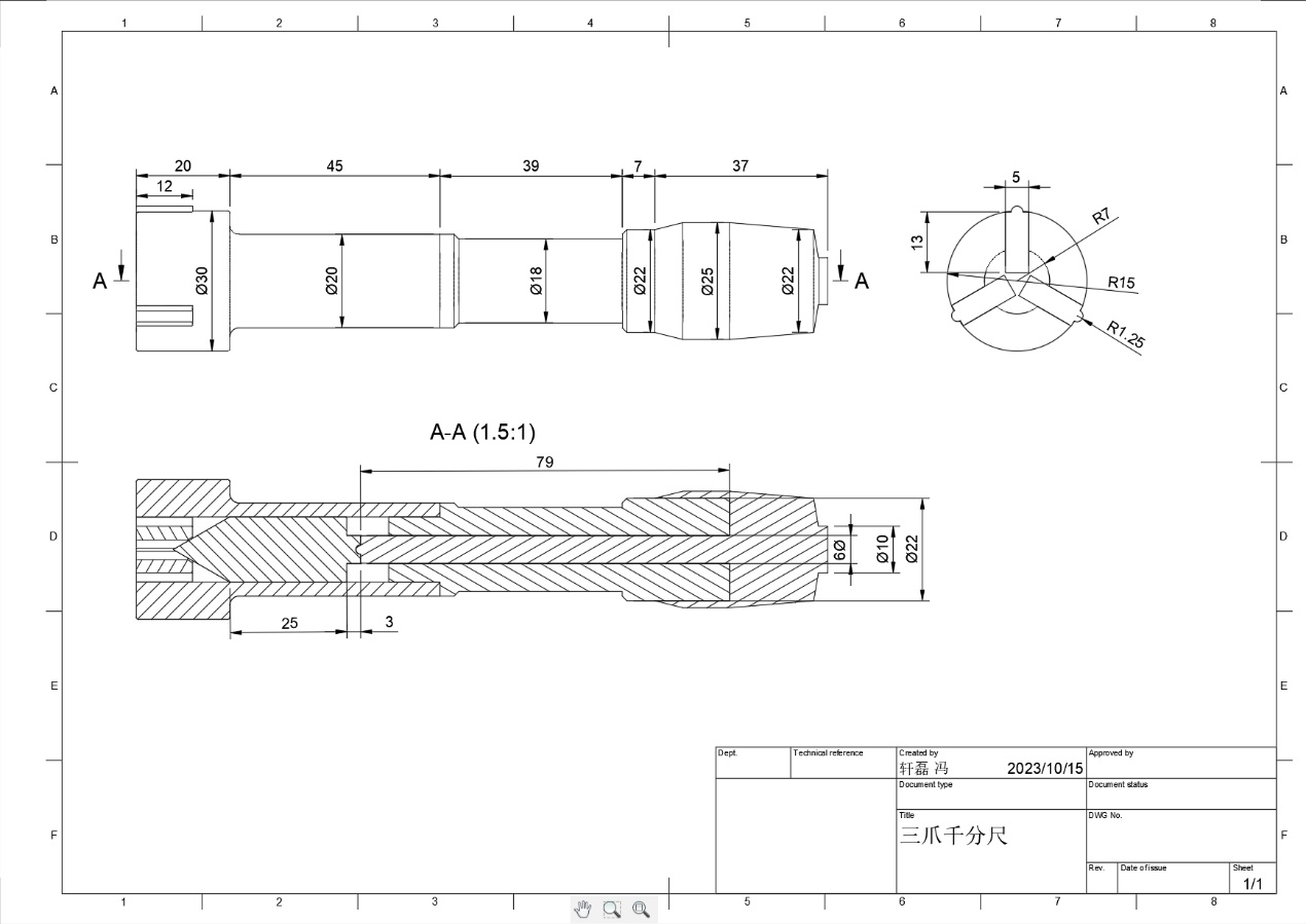
Other CAD Softwares
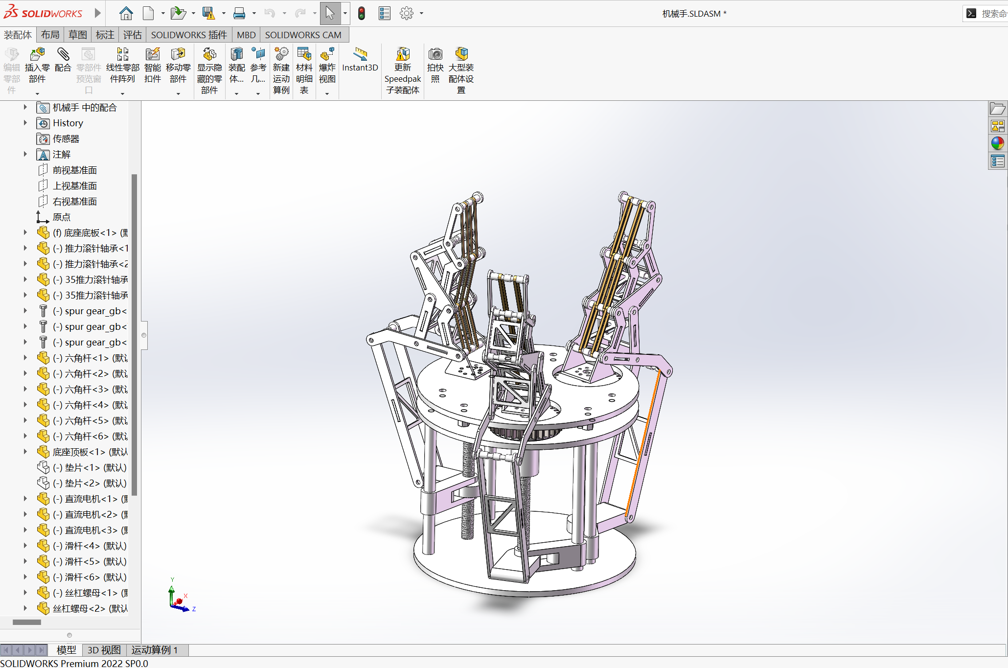
SolidWorks
What is SolidWorks?
SolidWorks software is a 3D CAD system, mainly used for the development of mechanical design products, with powerful, easy to learn and use, and technical innovation three characteristics.
History
SolidWorks software is the world’s first Windows based development of 3D CAD system, due to technical innovation in line with the development of CAD technology trends and trends, SolidWorks quickly became the most competitive CAD/CAM software. Worldwide, users spend 55 million hours using SolidWorks each year.
Characteristics & Benefits
- SolidWorks software is powerful, easy to learn, and innovative to provide different design solutions, reduce errors in the design process, and improve product quality.
- Provide a complete set of dynamic interface and mouse drag control scheme, reduce the design steps and redundant dialog box, make the design interface become more tidy.
- Feature templates provide a good environment for standard parts and standard features. Users can invoke standard parts and features directly from feature templates.
- The 3DExperience cloud collaboration platform enables product lifecycle management and collaboration, and ensures data security.
- When new parts are generated, users can directly refer to other parts and maintain this reference relationship. In the assembly environment, parts can be easily designed and modified. For large assemblies of more than 10,000 parts, user efficiency is greatly improved.
AutoCAD
What is AutoCAD?
AutoCAD is an automatic computer-aided design software first developed by Autodesk in 1982 for two-dimensional drawing, detailed drawing, design documentation, and basic three-dimensional design.
History
Autodesk was founded by John E. Walker in 1982, and later that year it launched AutoCAD, its first major computer-aided design program. After decades of development, AutoCAD is widely used in aerospace, construction, machinery, chemical industry and other fields.
AutoCAD has always maintained a high frequency of updates, and each new version is introduced with new design tools and new commands.
Characteristics & Benefits
- AutoCAD has powerful graphics drawing and editing functions, can be converted to a variety of graphics formats, and has strong data exchange capabilities. At the same time, AutoCAD has the characteristics of universality and ease of use, which can be adapted to a variety of hardware devices and can be used by various customers.
- PDF support: Users can input geometric shapes from PDF files into CAD and retain accuracy
in graphic features. - Object capture support: Users can specify precise positions on the attached coordination
model using standard 2D endpoint and central object capture. - Operation optimization: AutoCAD’s layer function allows users to edit different layers
individually, controlling the display and printing characteristics of graphics. - Command line: Users can execute all commands by entering the command name or
simplifying the command, improving the drawing efficiency.