Fourth, We Learned About the Concept of CNC and Cases.
Case analysis of CNC machining of automotive engine cylinder block
Article Catalog
- Case Background
- Processed Objects
- CNC Machining Process
- CNC Processing Equipment
- Material
- Processing Difficulties
- Note
- Case Summary
Case Background
1 Introduction
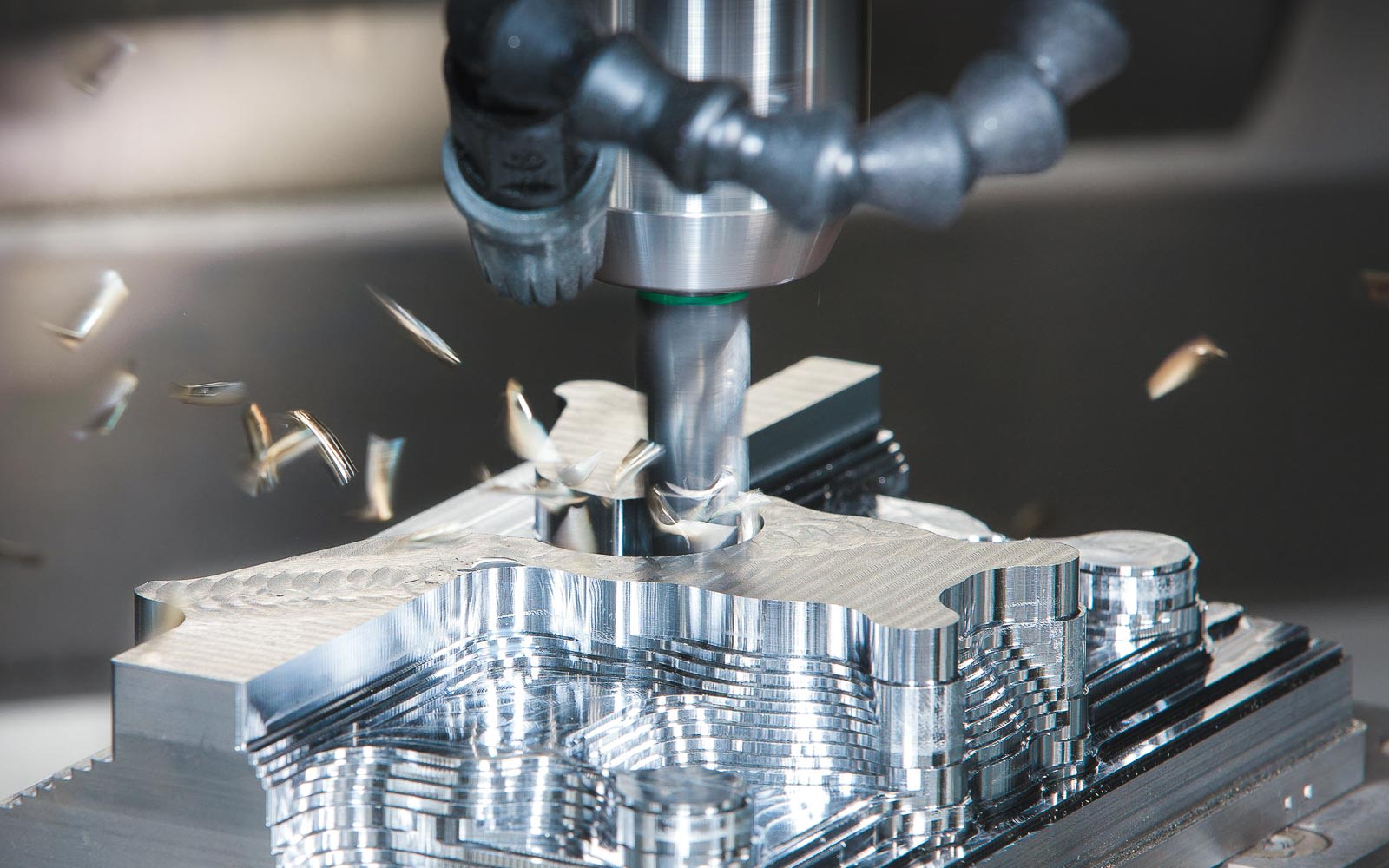
In the field of automotive manufacturing, the widespread application of CNC machining technology has become the key to manufacturing various important automotive components. Among them, the engine, transmission, braking, and steering systems all rely on high-precision and high-strength components. For example, the engine is the heart of a car, and its key components include the cylinder block, crankshaft, connecting rod, valve seat, etc. These components not only require complex geometric design, but also need to ensure high accuracy and quality during the machining process.
At the same time, in the transmission system, the gearbox gears, transmission shafts, and brake discs, pads, and other components in the braking system are key components of automotive performance and safety, and their manufacturing also requires high precision and quality.
It is particularly noteworthy that the complex shapes of engine blocks, cylinder heads, crankshafts, and other parts in automotive components make machining extremely difficult. The application of CNC machining technology has made the processing of these complex parts more precise and efficient. Through CAD design and CAM programming, CNC machining can achieve high-precision machining of these components, ensuring that they meet strict technical specifications and quality standards.
With the continuous development and upgrading of the automotive industry, the application prospects of CNC machining in automotive component manufacturing are becoming increasingly broad. Due to its advantages in improving production efficiency, reducing production costs, and ensuring product quality, CNC machining technology has become an indispensable and important link in the automotive manufacturing process.
This article analyzes a CNC machining case of using Zhongwang CAM to process the cylinder block of an automotive four cylinder engine.
2 Processing and application in the field of automotive parts
Engine parts processing: CNC machining can be used to manufacture various parts of engines, such as cylinder blocks, crankshafts, connecting rods, valve seats, etc. These parts require high precision and strength.
Transmission parts processing: CNC machining can be used to manufacture various parts of transmission systems, such as gearbox gears, clutches, transmission shafts, etc. These parts require high precision and strength.
Brake parts processing: CNC machining can be used to manufacture various parts of the brake system, such as brake discs, brake pads, brakes, etc. These parts require high precision and quality.
Processing of steering parts: CNC machining can be used to manufacture various parts of the steering system, such as steering gears, steering rods, steering machines, etc. These parts require high precision and strength.
Processed Objects
Automotive Four Cylinder Engine Block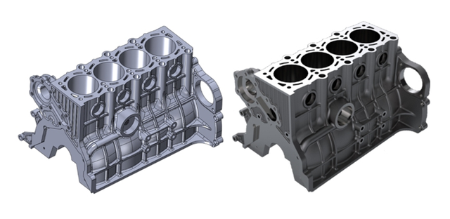
CNC Machining Process
The machining process of the engine cylinder block includes surface grinding, cylinder boring, and drilling. This article will generate the corresponding tool path through functions such as “top surface”, “spiral”, and “hole strategy” in Zhongwang 3D.
1 Surface polishing
Firstly, we need to process the cylinder block and polish off any excess parts to make it smooth.
This is crucial for ensuring good airtightness and accurate safety height.
We can achieve a smooth surface by using larger step lengths, flying knives, and higher machining accuracy.
The CNC machine tool will perform surface treatment on the cylinder block according to the specified safety height. We only need to set an appropriate surface depth to produce a very flat cylinder surface. The following is a specific operation method for generating surface grinding tool paths using the ‘Top Surface’ strategy.
Step 1: Select the “Top Face” strategy in the “2D Face” panel under the “2-axis milling” tab, then select “Outline” as the feature and assign the tool as D25R3.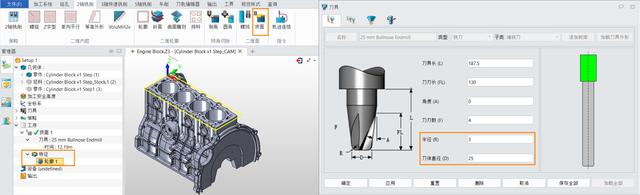
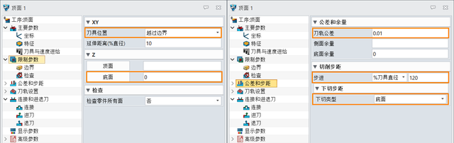
Step 2: Set key parameters, as shown in the following figure.
- In the constraints, set the tool position to “cross the boundary” and set the bottom to “0”.
- In “Tolerance and Step”, set “Tool Path Tolerance” to “0.01”, set “Step” to “% Tool Diameter” and assign a value of “120”, and set “Undercut Type” to “Bottom”.
After the calculation is completed, the tool path will be generated, as shown in the following figure.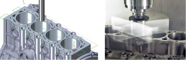
2 Cylinder boring
Next, we need to create a tool path for the boring hole, allowing the hard alloy cutting tool to cut off excess metal parts according to the set tool path, thereby increasing the boring hole. In this process, we need to control the machining accuracy well. In order to accurately and evenly process these four cylinders, we use the ‘Spiral’ function of Zhongwang 3D. The following are the operating steps for cylinder boring:
Step 1: Under the “2-axis milling” tab, in the “2D inner cavity” panel, click [Spiral].
Step 2: Select the contour of four holes as the machining feature and use the same tool as the surface polishing.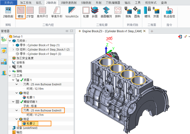
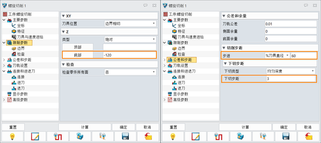
Step 3: Set key parameters, as shown in the following figure.
In the limit parameters, set the bottom to “-120”.
Set the boundary, step, and undercut step: Set “step” to “% tool diameter” and assign a value of “60”, and set the undercut step to “3”.
Set the connection and feed/retreat mode: Set the “feed mode” to “spiral”, set the “tilt angle” to “3”, and then set the “slow feed” and “retreat” as connections.
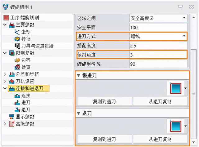
At this point, the generated tool path is shown in the following figure.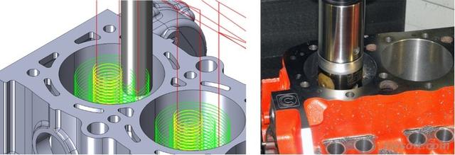
3 Drill
Finally, we need to drill holes in the engine block to machine the coolant channels and exhaust holes. With the help of Zhongwang 3D’s “Hole Strategy”, we can complete this part of the work in a very short time, as follows:
Step 1: Right click on “Strategy” in the machining manager panel, and then select “Insert Drilling Strategy” to generate “Hole Strategy”, as shown in the following figure.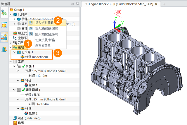
Step 2: Select the part as the machining feature and start the calculation. After the calculation is completed, the drilling tool path can be generated.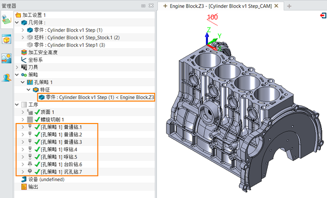
It is worth mentioning that the Zhongwang 3D hole strategy can automatically identify the types of holes on the engine cylinder block and generate drilling tool paths for different types of holes, thereby significantly improving programming efficiency.
4 Generate NC code
After generating all the tool paths mentioned above, we can output them as NC codes and then machine them for processing.
Step 1: Select the “FanucBasic” controller in the post processor configuration and set the device definition file to “machineuall” to complete the device definition.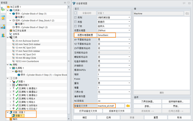
Step 2: Select all processes, output and obtain the NC code.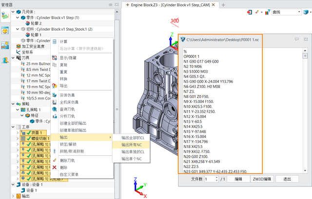
CNC Processing Equipment
CNC milling machine: used for surface polishing, smoothing excess parts of the cylinder block to ensure smooth and smooth surface. Capable of achieving large step distance, flying knife operation, and maintaining high machining accuracy.
CNC boring machine: used for cylinder boring, processing the cylinder to increase its diameter and ensure its size and accuracy. The “spiral” function of Zhongwang 3D can assist in controlling machining accuracy and uniformity.
CNC drilling machine: used for drilling and processing, including coolant channels and exhaust holes. Zhongwang 3D’s “hole strategy” can automatically identify different types of holes and generate drilling tool paths.
The above equipment plays a key role in the case, completing the machining process of the engine cylinder block. The combination of CNC milling machines, CNC boring machines, and CNC drilling machines makes various machining processes for engine cylinder blocks efficient and accurate. The tools and process settings used during the machining process, such as D25R3 tools and different machining parameter settings, are also key factors to ensure machining accuracy and quality. The entire machining process adopts different functions and strategies of Zhongwang 3D software, which can generate accurate tool paths in the CAD/CAM environment and guide the corresponding CNC machining equipment to complete the machining process of the engine cylinder block.
Material
1.Ductile iron blank: As the raw material for processing, it is used to make crankcase blank. This material has high toughness and strength, making it suitable for making crankcases for automotive engines.
2.Coarse and fine boring composite tools: Tools specifically used for cylinder hole processing, which can improve processing efficiency and improve the surface quality of cylinder holes.
3.CNC gantry machining center: a machine tool equipment used for machining cylinder holes, which can control the cutting tools through the CNC system for precise machining operations.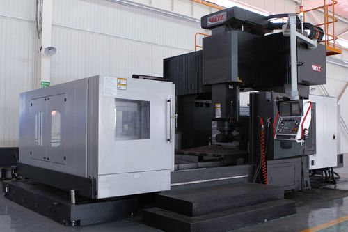
4.CAD/CAM software: Computer aided design/manufacturing software used for designing and generating tool paths, such as Zhongwang 3D, for developing machining strategies, programming, and providing cutting paths.
5.Positioning reference: The bottom surface and bottom edge are used as the main positioning reference to ensure the accuracy of positioning during the machining process, and to ensure key quality requirements such as the verticality of the cylinder hole, the geometric tolerance of the cylinder surface and edge.
6.R parameter programming: A universal machining program developed for milling cycles, automatic centering programs, and precision reference automatic input programs to improve program versatility and facilitate storage and invocation.
In summary, this case requires ductile iron blanks, professional cutting tools, CNC machine equipment, CAD/CAM software, accurate positioning benchmarks, and universal machining programs to complete the machining of the crankcase cylinder hole.
Processing Difficulties
The crankcase is made of whole cast blanks made of ductile iron, with a large volume and complex shape. The design requires high precision and is difficult to process. Here, a gantry machining center is used to process the cylinder hole of the crankcase. In order to obtain high-precision cylinder holes, three challenges need to be overcome.
Boring tools are prone to tool breakage: When using a double-edged boring tool to bore cylinder holes, especially the second ring of cylinder holes, it is easy to cause tool breakage problems. This is due to the large depth of the boring hole, reaching 488mm. To prevent tool breakage, only small cutting depths and feed rates can be used, which affects quality and efficiency. Therefore, composite specialized tools must be used.
Compilation of CNC machine tool control program: After milling the end of the cylinder hole, there are tool marks and the depth dimension is unstable. In order to fully utilize the functions and potential of the gantry machining center, it is necessary to develop a short, effective, and safe machining program. It is necessary to use the R parameter to program, especially to program the milling cycle CYCLE903 milling stop, and use the variable R to provide parameters for the cycle to reduce programming workload.
Clamping and alignment process: A reasonable alignment process must be developed for the characteristics of large volume, high accuracy, and complex shape of the workpiece.
Note
Five major considerations for CNC machining of automotive parts:
Choose appropriate CNC processing materials
Choosing suitable materials is an important step in the processing of automotive parts. Different automotive components require the use of different materials, so it is necessary to choose appropriate materials based on the requirements of the parts to ensure that they have good durability, strength, and heat resistance.Design and manufacture suitable fixtures
Fixture is an important tool in the machining process, which can ensure the stability and accuracy of the workpiece during the machining process. Therefore, it is necessary to design and manufacture suitable fixtures based on the shape and requirements of the parts to ensure accuracy and safety during the machining process.Choose appropriate CNC processing equipment
Choosing appropriate CNC processing equipment is also an important part of the automotive parts processing process. Different parts require the use of different processing equipment, such as CNC lathes, grinders, drilling machines, etc. It is necessary to select appropriate processing equipment according to the requirements of the parts to ensure accuracy and efficiency during the processing process.Adopting appropriate CNC processing technology
Different parts require different CNC machining processes, such as turning, milling, drilling, etc. It is necessary to choose a suitable CNC machining process according to the requirements of the parts to ensure the accuracy and surface smoothness during the CNC machining process.Strictly control the parameters during CNC machining process
Strictly controlling the parameters in the CNC machining process is also an important link in the CNC machining process of automotive parts. It is necessary to pay attention to controlling parameters such as cutting speed, cutting depth, and cutting amount during the CNC machining process to ensure accuracy and surface quality during the CNC machining process.
Case summary
Through this case study, we have identified several key points and some gains that are crucial for ensuring processing quality, improving efficiency, and promoting scalability.
Importance of positioning reference: As the main positioning reference, the bottom surface and bottom seam overlap with the process reference and design reference, which is crucial for key quality requirements such as cylinder hole perpendicularity, cylinder table surface, and seam geometric tolerance.
Professionalism in tool selection: The use of coarse and fine boring composite tools has improved production efficiency. The positioning of the tool handle increases the rigidity of the tool, thereby improving the surface quality of the cylinder hole.
Universality of programming: Various machining programs have been developed using R parameters, such as milling cycles, automatic centering programs, and precision benchmark automatic input programs, which improve the universality of the program and facilitate storage and invocation.
Reference
https://www.sohu.com/a/675811516_120371597
https://www.sohu.com/a/429435719_667240
https://baijiahao.baidu.com/s?id=1690729889214272974&wfr=spider&for=pc