Article Catalog
- Experiment 2-LED
- Experiment 3-Motor
- Experiment 4-Screen
Experiment 2-LED
Overview
The purpose of this experiment is to control two LED lights using Arduino, making them alternate in blinking to demonstrate the basic principle of digital LED control.
Materials
1 Arduino development board
2 LED lights
Jumper wires
Circuit connection method
We used ThinkerCAD to create the circuit diagram.
Circuit simulation after running the code.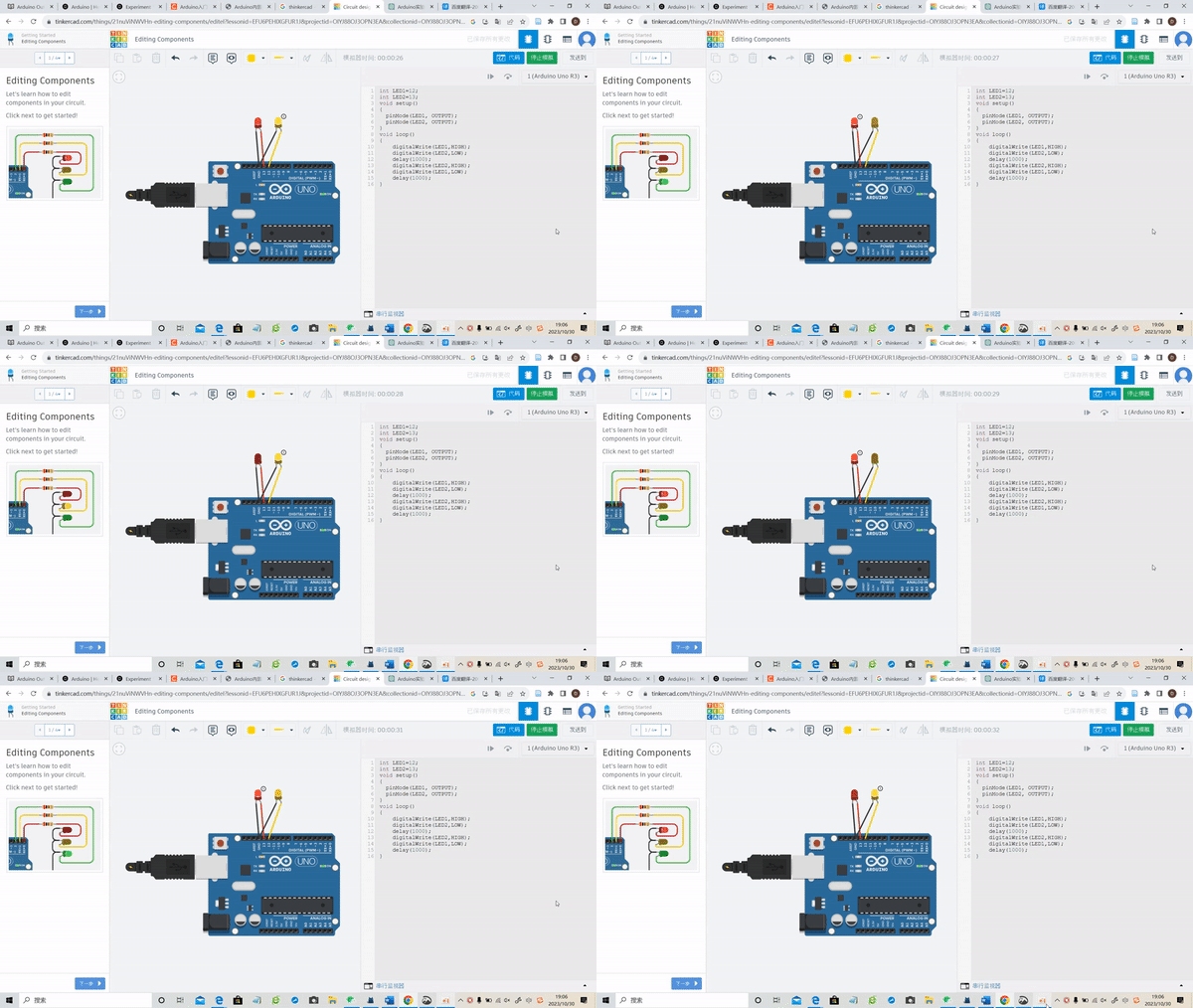
Production process
Connect two LED lights to digital pins 12 and 13 on the Arduino development board.
Write code in the Arduino programming language to create an alternating blinking effect between the two LED lights.
Compilation successful, upload successful.

The code is as follows:
1 | int LED1=12; |
Code Explanation:
int LED1=12; and int LED2=13;: Define LED1 and LED2 connected to digital pins 12 and 13 on the Arduino.
pinMode(LED1, OUTPUT); and pinMode(LED2, OUTPUT);: Set the pins as output to control the LED lights.
digitalWrite(LED1, HIGH); and digitalWrite(LED2, LOW);: Turn on LED1 and turn off LED2.
delay(1000);: Maintain the state for 1 second.
digitalWrite(LED2, HIGH); and digitalWrite(LED1, LOW);: Turn on LED2 and turn off LED1.
delay(1000);: Maintain the state for another 1 second.
Achievement display
LED1 and LED2 alternately blink, with one on while the other is off, each staying on for 1 second, then alternating states, creating an alternating blinking effect.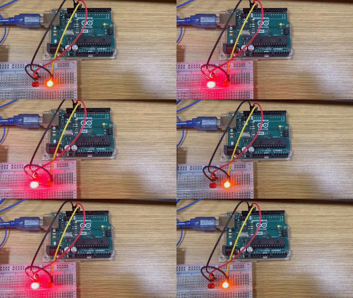
Conclusion
Through this experiment, we have learned how to control multiple LED lights with Arduino, displaying the principles of digital output pin control.
Experiment 3-Motor
Overview
This experiment utilizes an Arduino board to control a servo motor. The servo motor will perform a sweeping motion back and forth, rotating to three different positions - 0 degrees, 40 degrees, and 80 degrees sequentially with a delay of 1 second at each position.
Materials
1 Arduino development board
1 Servo motor
Jumper wires
Circuit connection method
Control principle of steering gear:
The servo motor is essentially a low-cost servo motor system. Its working principle is to receive a PWM pulse width modulation signal through an internal control circuit, and then control the rotation of the built-in motor. The built-in motor drives the series of reduction gear sets to transmit torque to the output shaft and steering wheel. The output shaft will be connected to a potentiometer used for feedback on angle position. Interconnected, when the steering wheel rotates, it will also drive the potentiometer to output a voltage signal, which is fed back to the control circuit inside the steering gear. The control circuit then determines the angle or speed of the steering gear rotation based on its position.
Production process
The SG90 servo has three wires: power, ground, and signal.
The power cord is usually red and should be connected to the 5V pin on the Arduino board.
The ground wire is usually black or brown and should be connected to the GND pin on the Arduino board.
The signal pins are usually yellow, orange, or white and should be connected to the digital pins on the Arduino board.
Connect the signal wire of the servo motor to digital pin 10 on the Arduino board.
Upload the provided code to the Arduino board.Compilation successful, upload successful.

The code is as follows:
1 | #include <Servo.h> |
Code Explanation:
The code employs the Servo library, allowing the Arduino to control the servo motor’s movement.
The myservo object is created to interface with the servo motor connected to digital pin 10 (PIN_SERVO defined as 10).
In the setup function, the servo motor is attached to the defined pin using myservo.attach(PIN_SERVO);.
Within the loop function, the servo motor is sequentially moved to four different positions: 0 degrees, 40 degrees, 80 degrees, 40 degrees (in reverse order), and back to 0 degrees.
After moving the motor to a specified position using myservo.write(angle);, a delay of 1 second (delay(1000);) follows before the next movement.
Observe the motion of the servo motor, which will move to 0 degrees, then 40 degrees, followed by 80 degrees and back to 40 degrees, with a 1-second pause at each position.
Achievement display
The servo motor performs a sweeping motion, rotating in the sequence of 0 degrees, 40 degrees, 80 degrees, 40 degrees, and returns to 0 degrees. It pauses for 1 second at each position.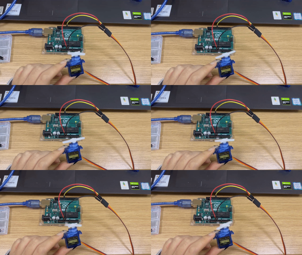
Conclusion:
This experiment demonstrates the precise control of a servo motor using an Arduino board. By specifying different angles, the servo motor is manipulated to move sequentially between multiple positions with timed delays. This experiment serves as a fundamental understanding of servo motor control and lays the groundwork for more complex applications involving precise motor positioning and motion control.
Experiment 4-Screen
Overview
This experiment aims to demonstrate the functionality of a 16x2 Liquid Crystal Display (LCD) using Arduino. The code will display “Hello, World!” on the first line of the LCD and continuously show the elapsed time (in seconds) since the Arduino board was powered up on the second line.
Materials
1 Arduino development board
16x2 LCD Display
Jumper wires
10K resistor
Circuit connection method & schematic diagram

Production process
Connect the 16x2 LCD display to the Arduino according to the specified pin configuration in the code.
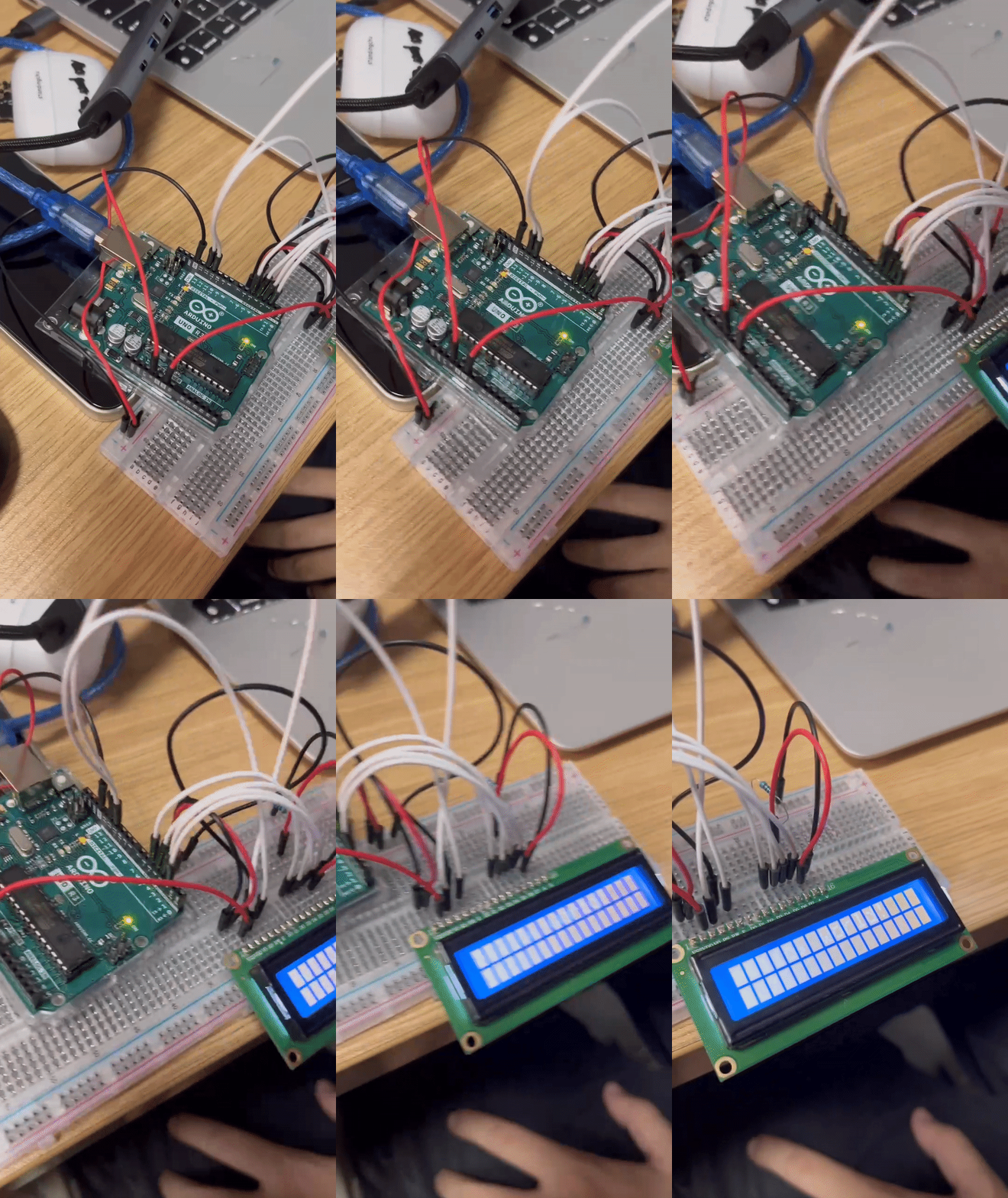
Upload the provided code to the Arduino development board.
Observe the LCD display, where “hello, world!” will be shown on the first line, and the elapsed time since power-up will be displayed on the second line.
We found that the screen brightness was too bright to see clearly, so we started adjusting the resistance and used a sliding rheostat.
This is a comparison between before and after adjustment, and it can be seen that there is a significant difference in the brightness of the screen.
The code is as follows:
1 | /* |
Code Explanation:
The code utilizes the LiquidCrystal library, compatible with the Hitachi HD44780 driver, enabling communication between the Arduino and the LCD display.
It initializes the library with the specified digital pins (12, 11, 5, 4, 3, 2) connected to the corresponding pins on the LCD.
In the setup function, it defines the dimensions of the LCD (16 columns, 2 rows) and prints “hello, world!” on the display.
The loop function continuously updates the second line of the display by setting the cursor to the second row and printing the number of seconds that have elapsed since the Arduino board was powered up (measured using the millis() function).
Subsequently, we added the function of breath screen on the basis of the original experiment. The code is as follows:
1 | void setup() { |


Finally, we added an infrared sensor to the original function, so that the screen initially displays “hello world”, and then turns off the LCD display when the infrared sensor value exceeds 250. At the same time, when the sensor is not triggered, the display shows the number of seconds that have passed since startup.
The code is as follows:
1 | include <LiquidCrystal.h> |


Achievement display
Upon executing the code, the LCD will display “hello, world!” on the first row and continuously display the number of seconds since the Arduino was powered up on the second row.
Status after adding screen rest function: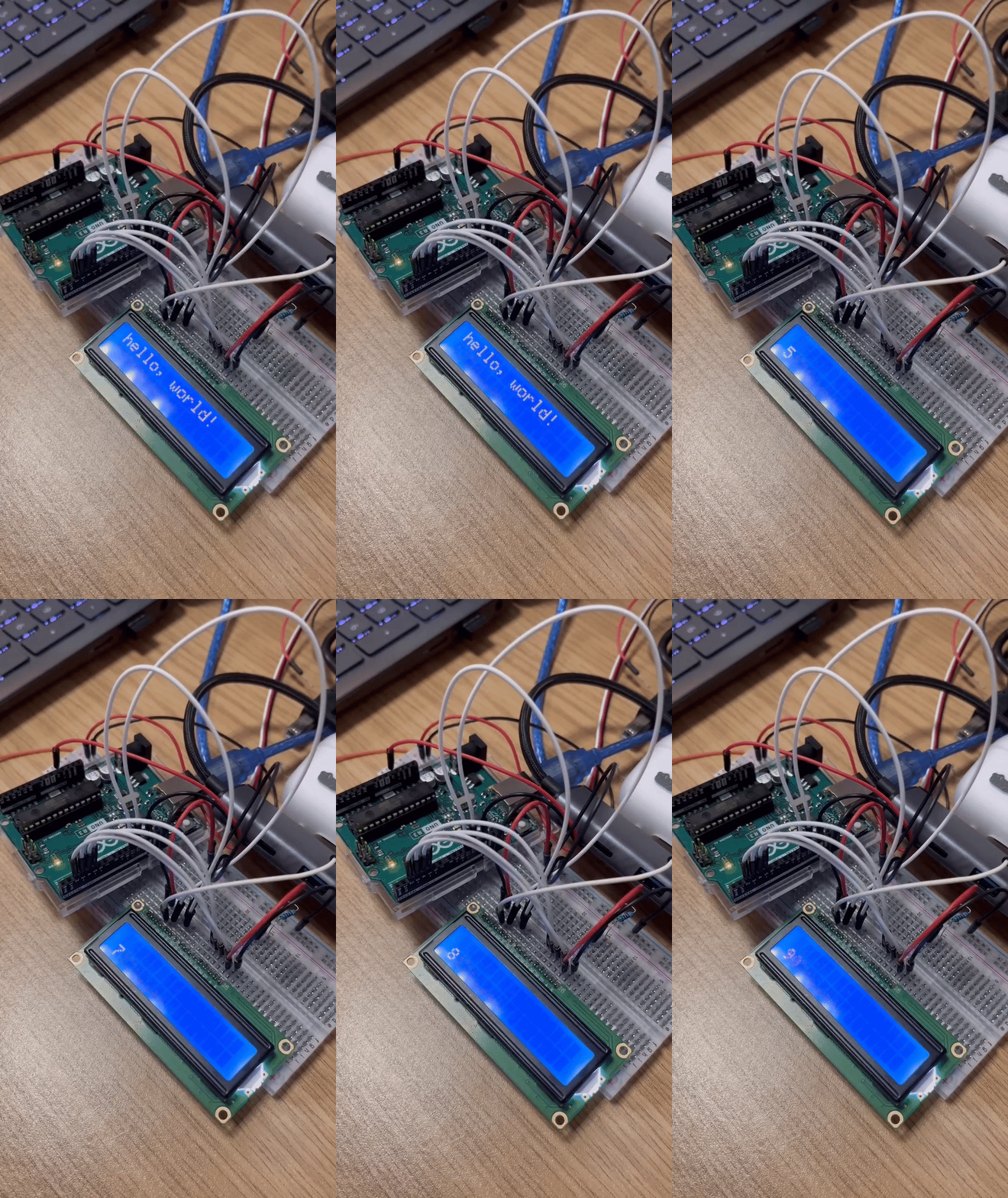
Status after adding an infrared sensor: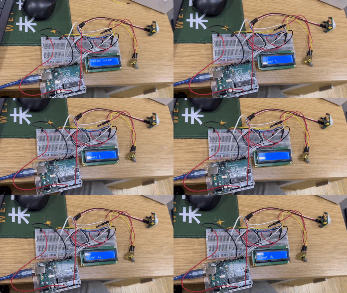
Conclusion
This experiment demonstrates the use of an LCD with an Arduino board to output text and dynamically update information on the display. It illustrates the basic functionality of an LCD and its integration with an Arduino, showcasing a simple text display and real-time information presentation.
Reference
https://www.nexmaker.com/doc/5arduino/Arduino_output.html
https://docs.arduino.cc/learn/electronics/lcd-displays
https://www.zhihu.com/question/459546366?utm_id=0
https://zhuanlan.zhihu.com/p/643197865