Article Catalog
- KaboomBox
- Animatronic Skull With Arduino
KaboomBox
01 Name
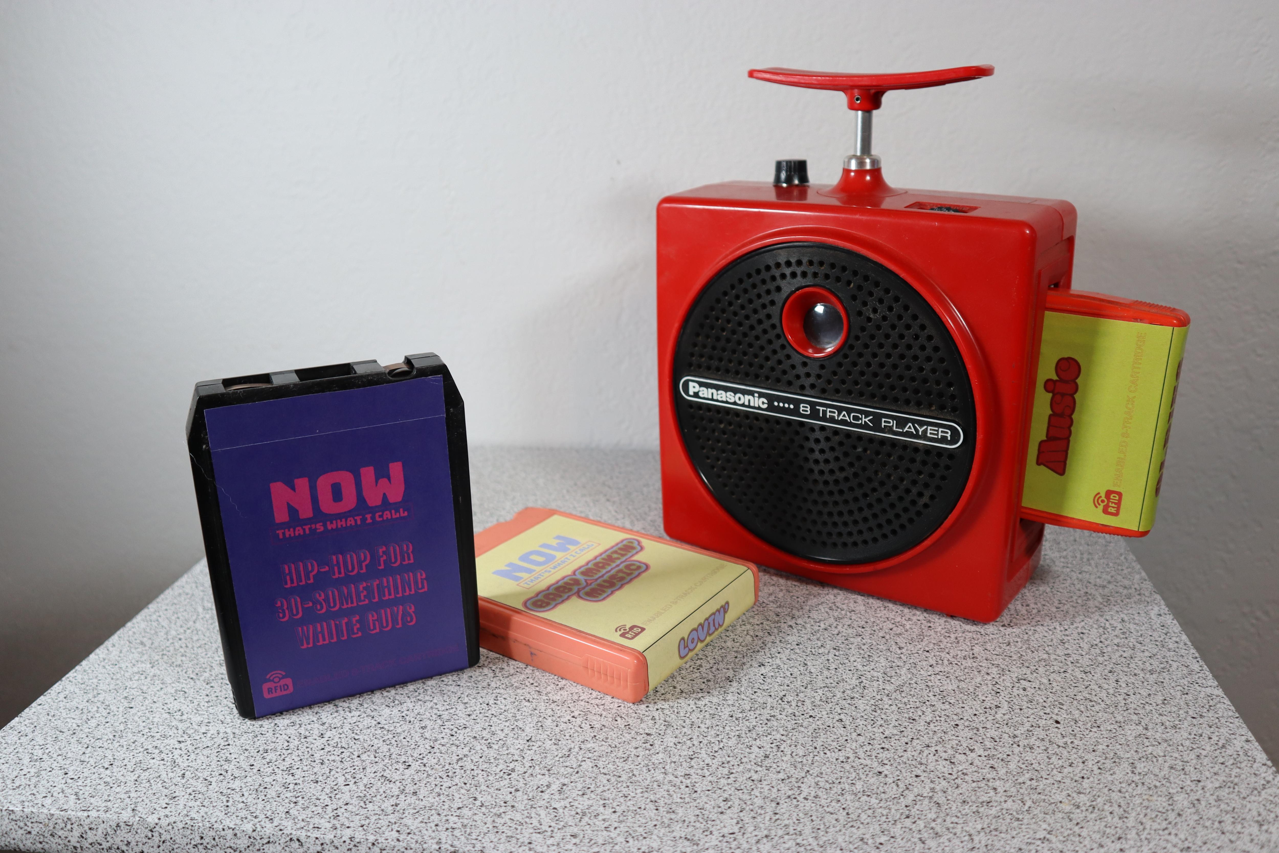
KaboomBox - an RFID 8-Track Player
02 Case Source
https://www.instructables.com/KaboomBox-an-RFID-8-Track-Player/
03 Case analysis
Vinyl records provide nice, warm analog sound. CDs have nearly lossless storage for high-quality music. Even cassette tapes have a certain nostalgic appeal and cool factor. But 8-track cartridges are almost useless, because they don’t offer any real benefits over the alternatives.
8-track players, on the other hand, can be very special.
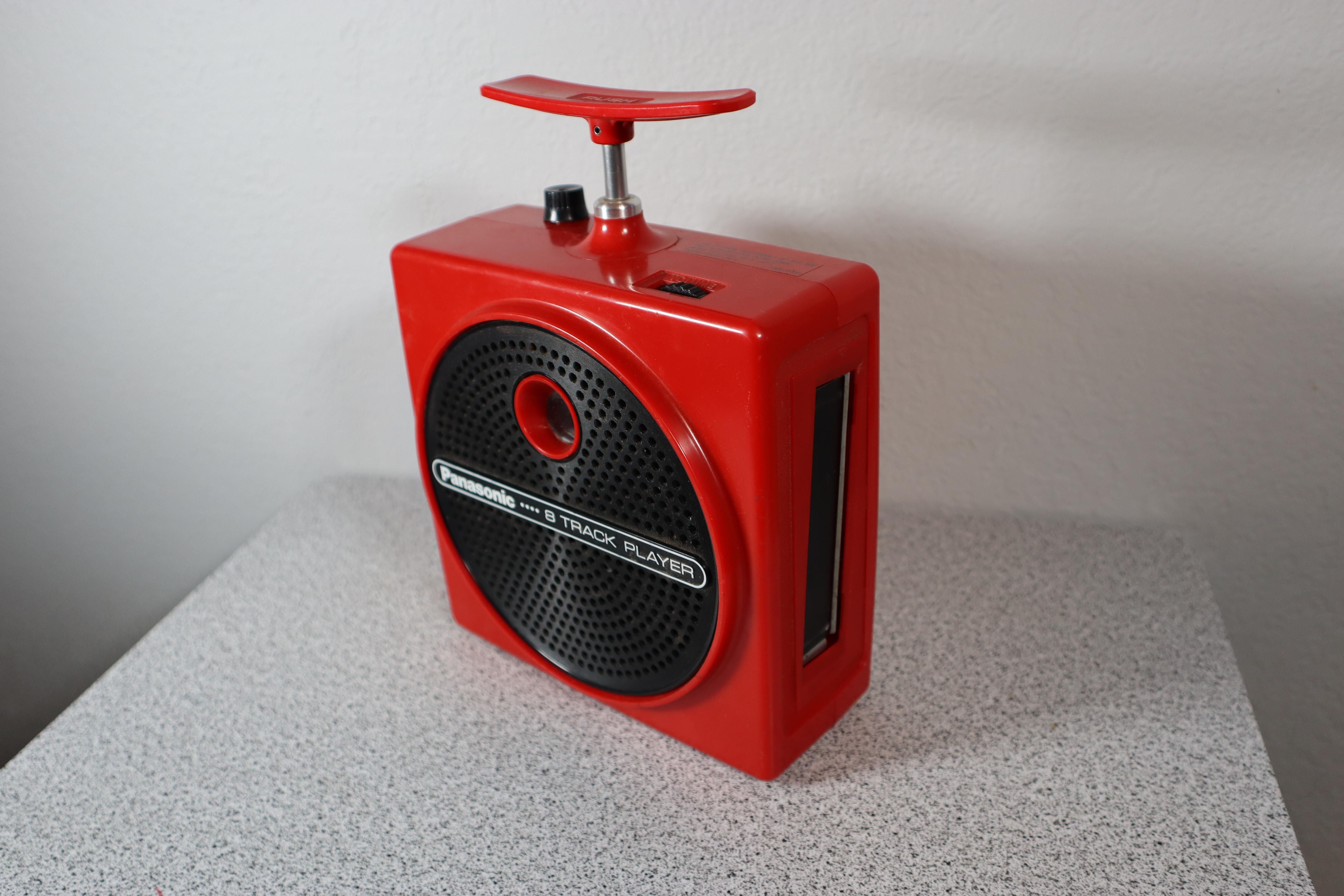
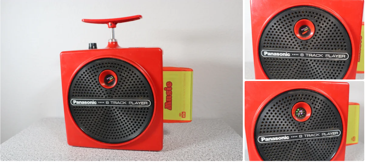
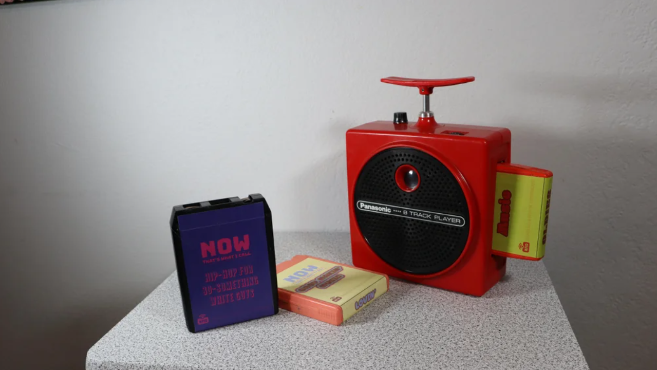
The best of the bunch is the Panasonic RQ-830S 8-track player, often called the “dynamite” or “TNT” due to the enclosure and next-track switch looking like an old school plunger detonator for explosives.
The blogger purchased a Panasonic RQ-830S, made in the ‘70s, that wasn’t functional. It was missing the battery cover and power supply, and wouldn’t turn on.
Then I turned it into the most awesome RFID music player this side of the new millennium.
An RFID music player is a fancy MP3 player that uses RFID (Radio Frequency Identification) tags instead of buttons to select music. In this case, there is an RFID sticker under the label of each 8-track cartridge. When the user inserts a cartridge, the device reads the RFID tag and triggers an associated folder of MP3 music on an SD card. That music then plays through a DFPlayer Mini MP3 player.
Supplies
Raspberry Pi Pico
DFRobot DFPlayer Mini MP3 Player
HiLetgo 0.95” SSD1331 65K OLED
HiLetgo PN532 RFID Reader
Software:
Autodesk Fusion 360;Arduino IDE;Adobe Illustrator or any image editor (for labels)
Tools:
3D printer;Soldering iron
Step 1: The Idea
The project, which the blogger’ve dubbed “KaboomBox”, works like most RFID music players. It reads an RFID tag and begins playing a folder of music linked to that specific tag.
Step 2: The Hardware
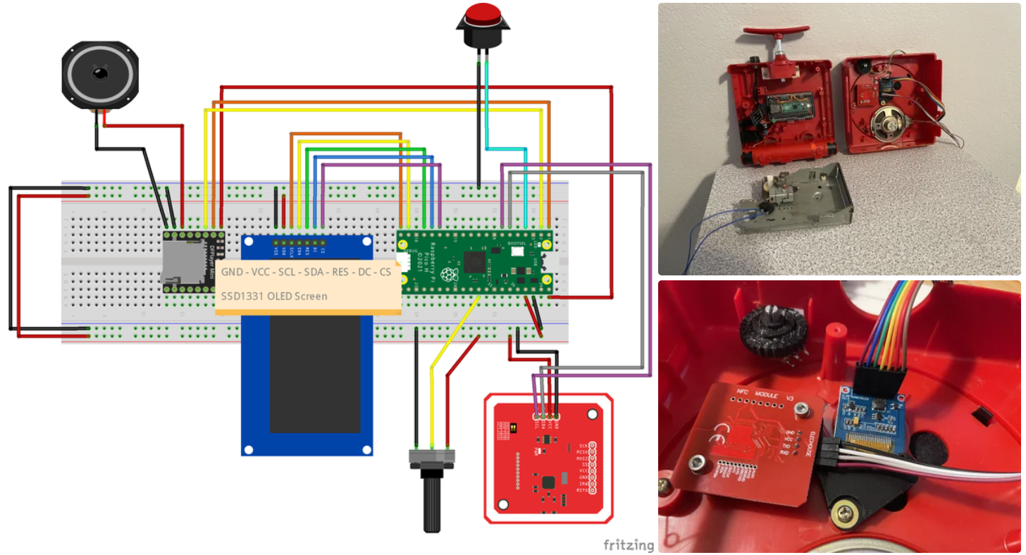
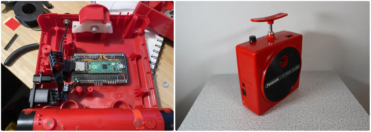
The “brain” is a Raspberry Pi Pico microcontroller development board.
That looks for RFID tags using a HiLetgo PN532 RFID reader. When it sees a tag, it tells a DFRobot DFPlayer Mini MP3 player to start playing songs in the corresponding folder on the micro SD card. An extension makes that SD card accessible on the exterior of the device.
The Pico also controls the LCD screen behind the window. At launch, it shows the Kaboom Box logo. Then it shows a waiting icon. When it detects an RFID tag, it display a music note icon with that playlist’s title in the middle. A circle of green dots around the outside indicate the volume level.
A potentiometer attached to the volume knob tells the Pico the volume to set. The Pico then gives the command to the DFPlayer to set the volume.
The plunger on top pushes down on the original mechanism, which has a really nice tactile feel. At the end of its travel, it hits the lever of a microswitch. The Pico registers that and tells the DFPlayer to move to the next song.
Power comes from a battery pack with two 18650 lithium battery cells. That goes through a charging/distribution board to the rest of the circuit via a lamp-style power switch mounted on the top of the device. A USB-C extension makes the charging port accessible from the outside.
Step 3: Custom Parts
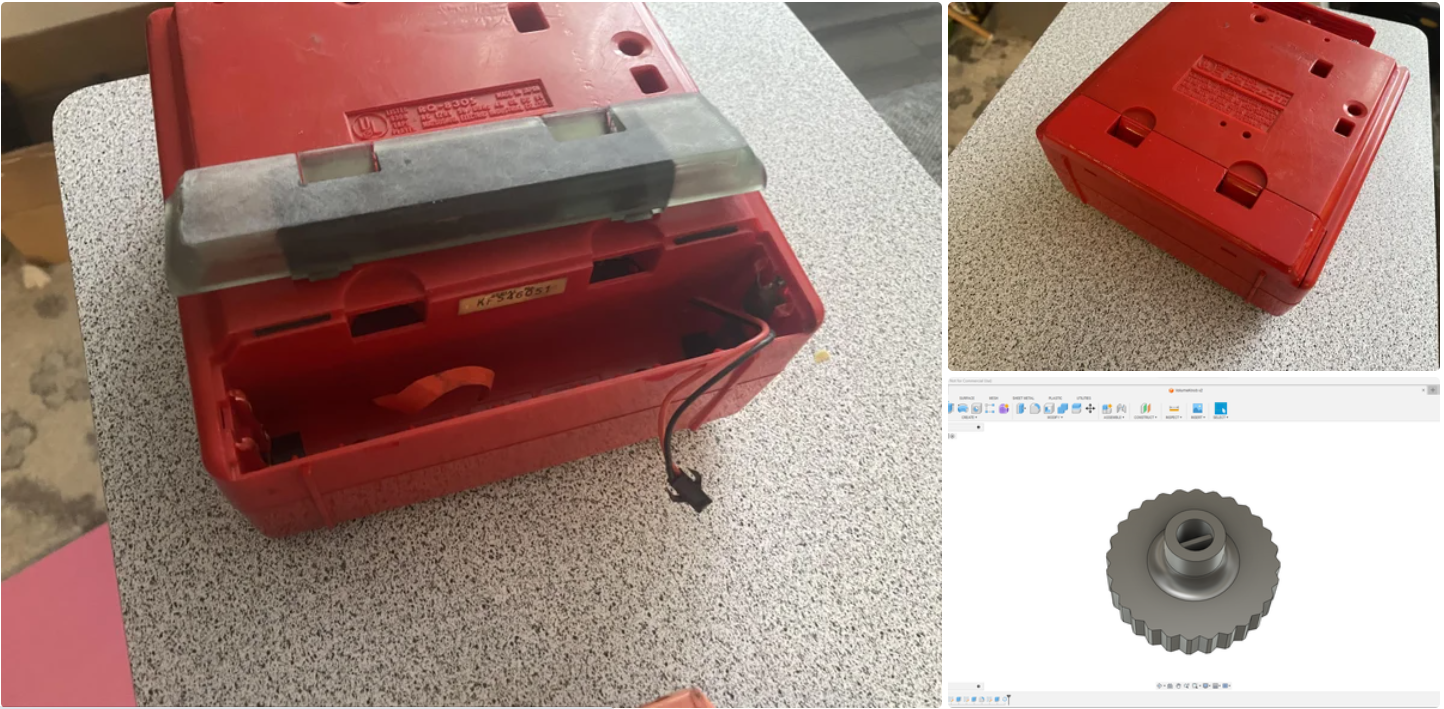
This project required a handful of custom 3D-printed parts, which the blogger designed in Autodesk Fusion 360.
These parts were the most difficult part of the project. It is always more of a challenge to design parts that fit existing devices when the entire device is your own creation. the blogger wish he had some secret approach to this, but he don’t. The blogger tried 3D scanning the enclosure, but couldn’t get good scans.
So he took the tried and true approach: measurements with digital calipers and trial-and-error through several iterations of the printed parts.
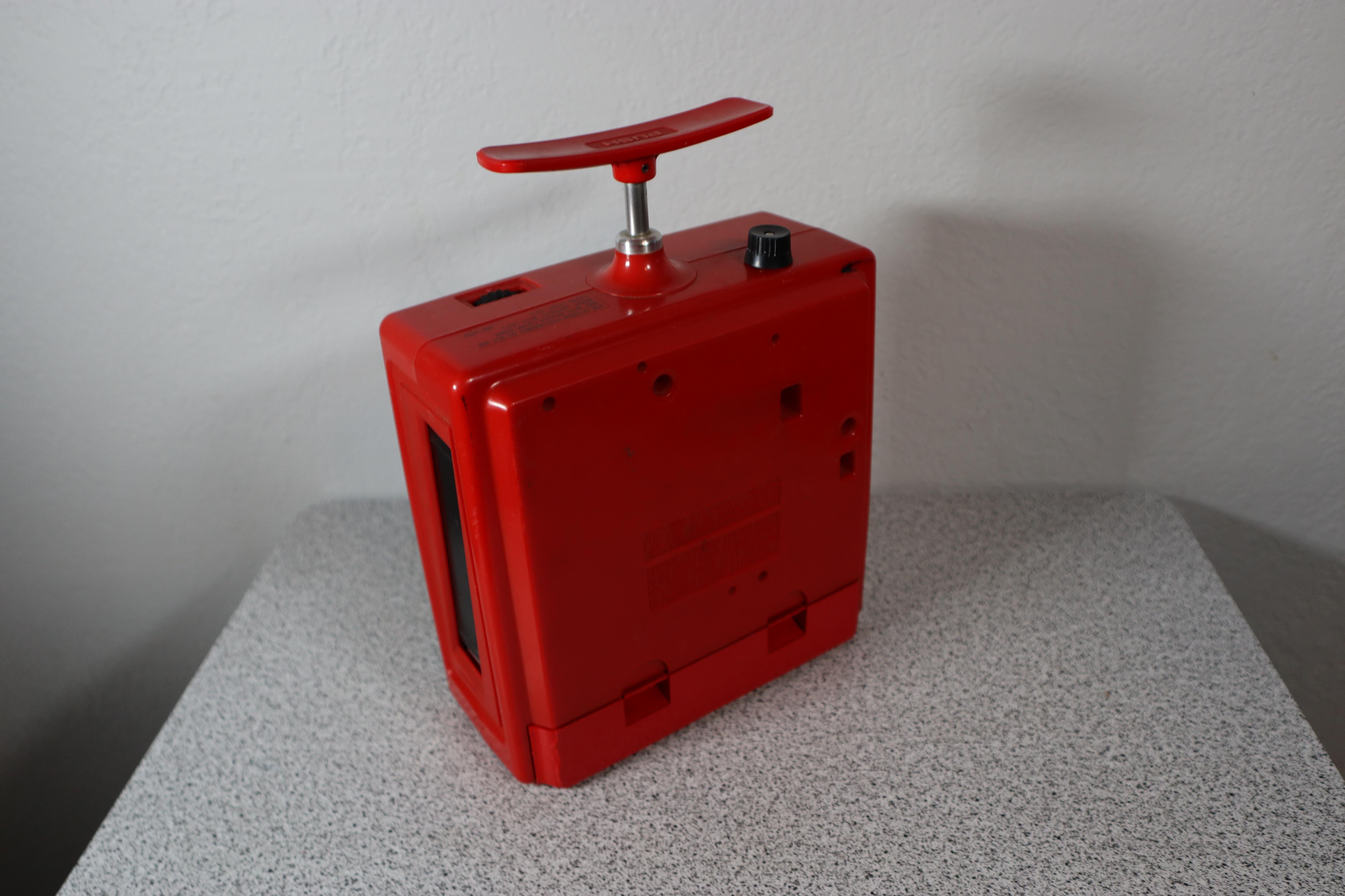
The most obvious is the battery cover, which was necessary since the original was missing. He very carefully designed that to match the curves of the device. He then printed it on a Phrozen Sonic Mighty 8K resin 3D printer to get the best quality and strength. Finally he spray-painted it with a color chosen to match as closely as possible.
Other 3D-printed parts include:
SD card port
USB-C port
Volume knob
LCD and RFID reader mount
Mount for the ElectroCookie prototyping PCB
Step 4: The Code
The blogger mentioned that all of the programming was performed within the Arduino IDE, which allowed him to take advantage of several handy libraries for the display, DFPlayer Mini, and RFID reader.
The blogger’s code was very thoroughly commented, so anyone interested in understanding all of the details was advised to look at the comments. Most of the code was straightforward and similar to what one would see in any RFID music player project. However, there were some quirks with the display that he wanted to talk about.
The display he used was a full-color OLED that he really liked, and he aimed to take advantage of its color capabilities. However, microcontrollers have limited memory and can struggle to display color images, as most high-resolution color displays handle their own storage and processing for that reason. He had to employ a few tricks to work around this limitation.
For example, the boot logo was actually composed of three different monochrome images, each displayed one at a time, with each set to a different color.
In a similar manner, the display shown when playing music was made up of various elements. The music note icon was a monochrome image, and the playlist name displayed over it was just text. He used the Adafruit GFX library to draw the green dots for volume control, and black dots were drawn over them to “erase” them when necessary. This method might not have been as memory-efficient as he would have liked, but it achieved the necessary visual effect.
Step 5: The Tapes
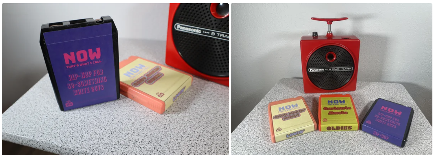
The most enjoyable part of the entire project, he found, was when he began with the purchase of a few old 8-track cartridges. He noted that these cartridges were very affordable and easily obtainable on eBay.
A considerable amount of time was spent on determining the optimal placement for the RFID tags. He discovered that precise positioning was crucial for reliable tag reading.
The final step involved creating his own labels, despite not being a professional graphic designer. This part of the project was enjoyable for him. He took care to ensure that the artwork files were created at the correct size to avoid any scaling issues.
With the appropriately sized artwork files in hand, he visited a FedEx print office to have them printed onto sticker paper. The correctly sized labels were then easily peeled and applied to the tapes, covering the RFID tags.
Step 6: The Music
The DFPlayer Mini does impose specific rules regarding file limits and folder organization.
In general, each folder is capable of accommodating up to a hundred songs, and you can create a hundred such folders. This effectively allows for a library of 10,000 songs, providing ample room for creating new tapes. The advantage of using an external SD card is that it allows for straightforward additions of new music.
However, one limitation is the absence of a programmed function for adding new RFID tags. Consequently, to create additional tapes with new tag IDs, you need to establish a connection and reflash the Pico.
Step 7: Enjoy!
04 Reproducibility
Complexity
The project is relatively complex, involving multiple hardware components (such as RFID card reader, music player, OLED display, etc.) and programming knowledge. As beginners, we may need some additional time to understand and master how these components work and how to integrate them.
Resource Requirements
The project uses some specific hardware, such as the Raspberry Pi Pico and a particular model of the RFID card reader. We need to ensure that we can access these hardware components. Additionally, custom parts like 3D printing and designing labels may require additional equipment or services.
Programming
The project involves programming, and we need to be proficient in the Arduino programming language and the use of relevant libraries. Handling aspects like displays and audio might require additional learning.
05 Evaluation (Value Point)
Advantages (Value Points)
Unique Vintage Design: The project preserves the captivating design of the original Panasonic 8-track player, adding a nostalgic and distinctive touch to the integration of modern technology into a retro device.
Seamless Component Integration: The project impresses with its meticulous attention to detail in packaging and the seamless integration of electronic components. While the original hardware has been replaced, the project maintains an authentic appearance. Key components such as the LCD screen, plunger switch, volume knob, SD card slot, and USB-C charging ports seamlessly fit into their original locations, preserving the continuity of the original design.
Potential Drawbacks
Power Switch Location: The use of a “lamp-style” power switch mounted on the top of the device may not be the most ergonomic choice. It’s advisable to explore the integration of the power switch into the original volume control or seek a more natural location, such as the back of the device, to enhance the authenticity of the project and user experience.
In summary, this project offers unique design and execution features but also presents opportunities for improvement to enhance the overall user experience and reproducibility.
06 Application
Music Exhibitions and Museums
Similar technology and design principles can be used in music exhibitions and museums to enhance visitor interaction. By embedding RFID tags into music exhibits or displays, visitors can easily access information about musicians, works, or historical events while enjoying music playback.
Tourism and City Guided Tours
Embedded technology and RFID tags can be used to create interactive city guided tour systems. Tourists can swipe cards or scan tags to access information about historical landmarks, attractions, or museums, while enjoying audio tours.
Children’s electronic diary
RFID Technology:
Consider using RFID technology to implement different sections of the children’s diary, such as pages for different dates or themes. Embed an RFID tag on each page, and when a child swipes a card or turns to a specific page, the corresponding voice or story can automatically play.
Embedded Audio Player:
Similar to the DFP layer Mini in the case, you can integrate a small embedded audio player to store and play the children’s voice recordings in the diary. This can be used to create sound pages where children can record their voices on different dates or themes.
Interactive Design:
Borrow interactive design principles from the case to create a visually engaging children’s diary. For instance, when a child turns to a specific page, the screen can display images or animations related to that page’s content and play the corresponding voice recording. This can spark a child’s interest and provide more interactivity.
Animatronic Skull With Arduino

01 Case Source
https://www.instructables.com/Animatronic-Skull-With-Arduino/
02 Case review
Project Overview:
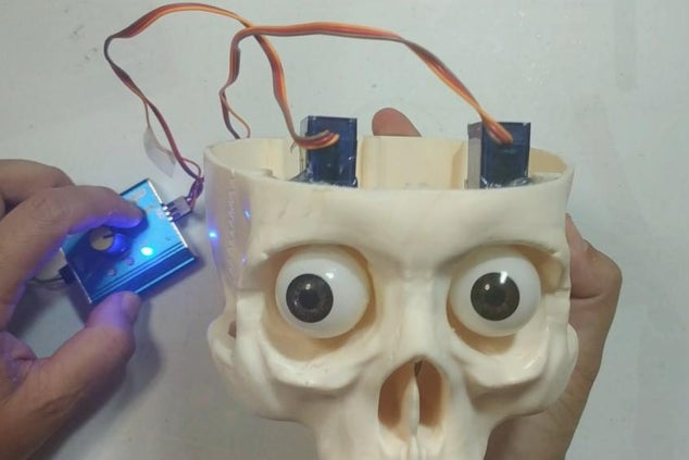
This animatronic skull consists of two 5mm red LEDs for the eyes and three micro servo motors for eye and jaw movements, creating realistic expressions. But what makes this skull truly special is its ability to react to its environment. It is equipped with an ultrasonic sensor (HC-SR04) that detects the proximity of objects, allowing the skull to react differently when someone approaches or moves away. Eye and mouth animations vary in speed and intensity, providing an interactive and immersive experience for anyone nearby.
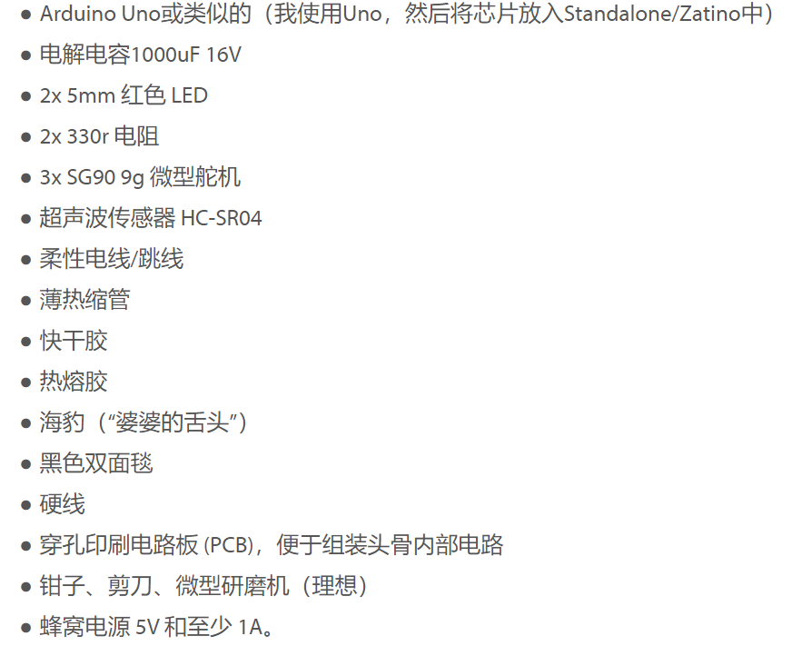
Necessary materials:
An ancient skull from National Geographic’s “The Human Body” collection
Arduino Uno or similar (I used the Uno and then put the chip in the Standalone/Zatino)
Electrolytic capacitor 1000uF 16V
2x 5mm red LEDs
2x 330r resistors
3x SG90 9g micro servos
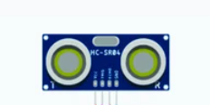
Ultrasonic Sensor HC-SR04
Flexible Wires/Jumpers
Thin Heat Shrink Tubing
Quick Glue
hot glue
Seals (“mother-in-law’s tongue”)
Black Bidim Blanket
Rigid wire
Perforated Printed Circuit Board (PCB) to facilitate assembly of the skull’s internal circuit
Pliers, scissors, micro grinder (ideal)
Cellular Source 5V and at least 1A.
Step1:Eyes

1 - Make the holes for the eyes, using the micro-grinder.
NOTE: The size of the hole must be sufficient to fit the servo motor shaft so that it does not lock/lock in the hole to prevent the motor from burning;
2 - Cut the “flap” of the servomotor to fit the skull (see photo);
3 - Glue the servomotor with hot glue;
4 - Cut the eye socket and discard;
5 - Cut the plastic “arm” of the servo motor to place the round part with quick glue on the top of the eye;
6 - Fit the eye onto the servo motor.
Step2:Testing the Angle of the Eyes
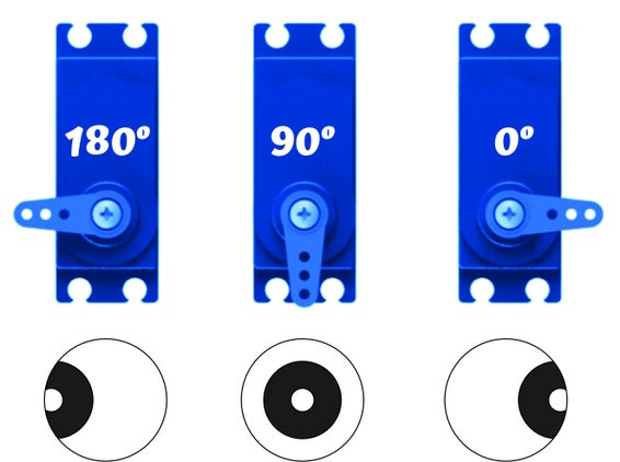
Place your eyes in the right position, with the central axis being “looking straight ahead at 90º”;
Looking in and out: 50º or 130º
Step3:Hole for Passing Wires
Drill the hole in the skull to pass the rigid jaw wire through.
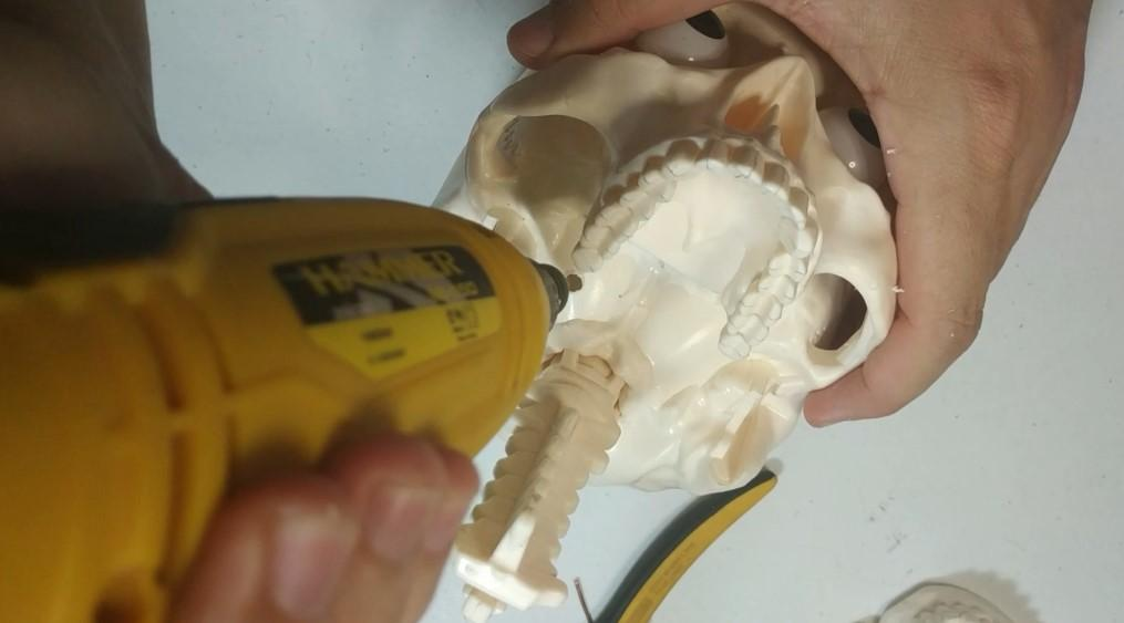
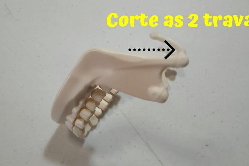
Step4:Jaw
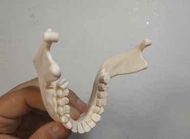
1 - Cut the 2 locks on the Jaw;
2 - Make a hole on the side of the jaw to fit the rigid wire;
3 - Glue the jaw servo motor to the skull (see photo);
4 - Take a stiff wire and bend a small piece of the end, leaving it in an L shape, to fit into the hole in the jaw and the other end of the wire to pass through the hole made in step 2.
5 - The jaw servo motor also contains a piece of wire with the tip bent, to fit the wire coming from the jaw.
OBS: The angle of the jaw servo, I put it as follows:
mouth closed: 140º
semi-open mouth: 110º and 90º
mouth open: 70º
Step5:Connections
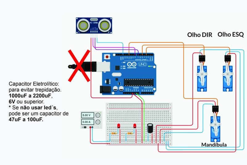
1 - Make the connections as shown in the diagram;
2 - Make another hole at the bottom of the skull to pass the servo motor signal wires (orange wires) along with the live and neutral wires that go on the printed circuit board.
OBS: Use Arduino Uno or another one of your choice.
Step6:Ultrasonic Sensor HC-SR04 and Final Assembly
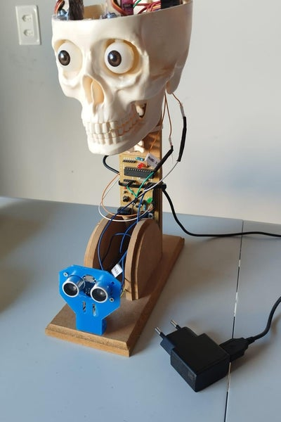
1 - Place the ultrasound sensor in front of the skull, as close as possible to the eyes, to simulate that the skull will look cross-eyed when it is in front of the eyes;
2 - Make a wooden support like mine or anything else to hold the skull, use your creativity.
3 - Cover the entire electronic part with a bidim blanket or another dark cloth to hide the electronic part (except the sensor).
Step7:SKETCH
1 | // MOUTH: |
03 Case Analysis
This skull can perform eye and jaw movements, making it a fascinating and immersive piece of electronic art.
This case uses ultrasonic sensors to detect the approach and movement of people, allowing the eyes of the skull to move accordingly. This form of interaction is really interesting.The design of using a servo to control the rotation of the skull’s eyeballs is very natural, and the presentation effect of the work is very good.
Place the ultrasonic sensor in front of the skull, as close to the eyes as possible, simulating that the skull will look cross-eyed when it is in front of the eyes. It’s simple and fun, and makes the skull seem like it’s really alive.
04 Reproducibility
1.Using ultrasonic sensors, the sensitivity is very high, and the code writing logic is easier to understand for students who have no coding foundation.
2.The product has less mechanical structure and will not be unable to be reproduced due to dimensional errors.
3.The raw materials required for this case are relatively easy to purchase and there are no special materials.
4.The case triggering process is relatively simple and is less likely to cause confusion.
05 Application
1.Compared with traditional works, electronic art works have much room for development.It can be used in exhibition halls, streets and other places
2.Although this project seems relatively simple, it has a wide range of applications and may be added as part of our final project.
3.Ultrasonic sensors and steering gears are relatively commonly used components, and their use in this case is of great reference for our future projects.
Reference
https://www.instructables.com/KaboomBox-an-RFID-8-Track-Player/
https://www.instructables.com/Animatronic-Skull-With-Arduino/