Secondly, We Started Experimenting with Fusion 360.
Article Catalog
- How to use Fusion 360
- Introduction to Creo
- Introduction to Solidworks
- Comparison of Creo and Solidworks
- Reference
How to use Fusion 360
We modeled a “cat and mouse sledgehammer” setup using fusion 360, which is divided into six main parts:
- Add plugin
- Ideas for Structure
- Parts Modeling
- Parts Assembly
- Decoration and Beautification
- Model Rendering
- Engineering Drawings
00 Add plugin
Enter the App Store, select fusion360, and view the relevant programs and plug-ins.
Click on it to select a plug-in.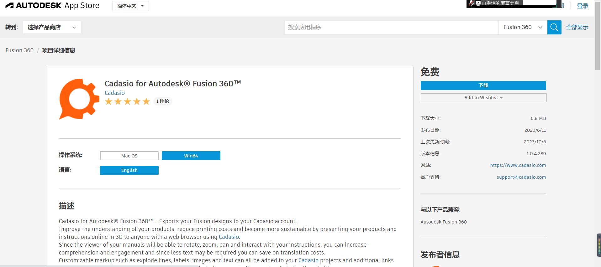
Log in to your fusion360 account.
Start the installation.
The plug-in was installed successfully.
01 Ideas for Structure
After browsing through many mechanical structures, it was decided to innovate the design based on the mechanical structure of the pendulum and introduce the incorporation of a gear structure to create a new cat and mouse desktop fun manual pendulum.
Pendulum Basic Mechanics:
Cat and Mouse IP:
02 Parts Modeling
Part fabrication (The first One)
Create sketches.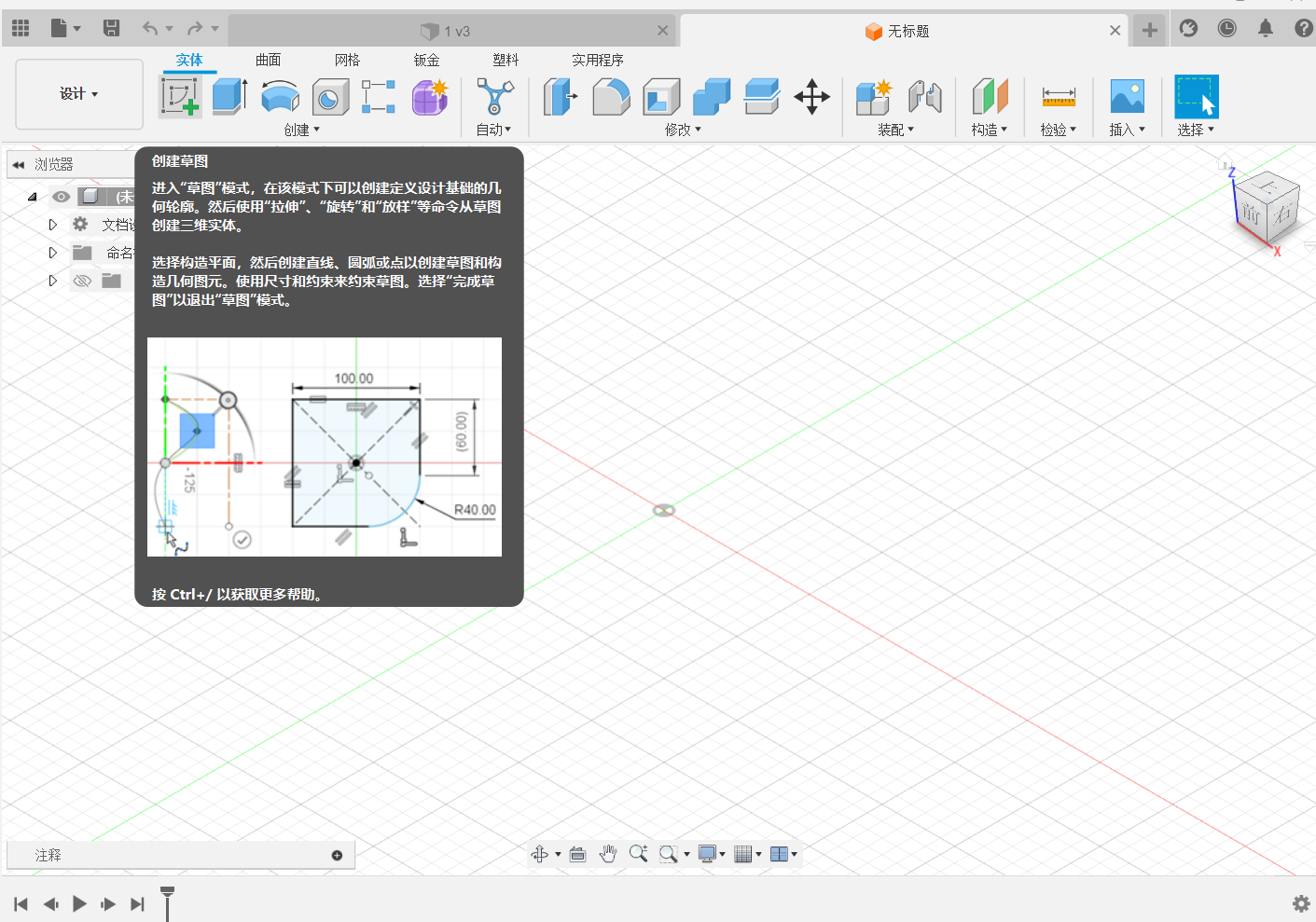
Select a plane or a flat surface.
Enter the sketch drawing mode.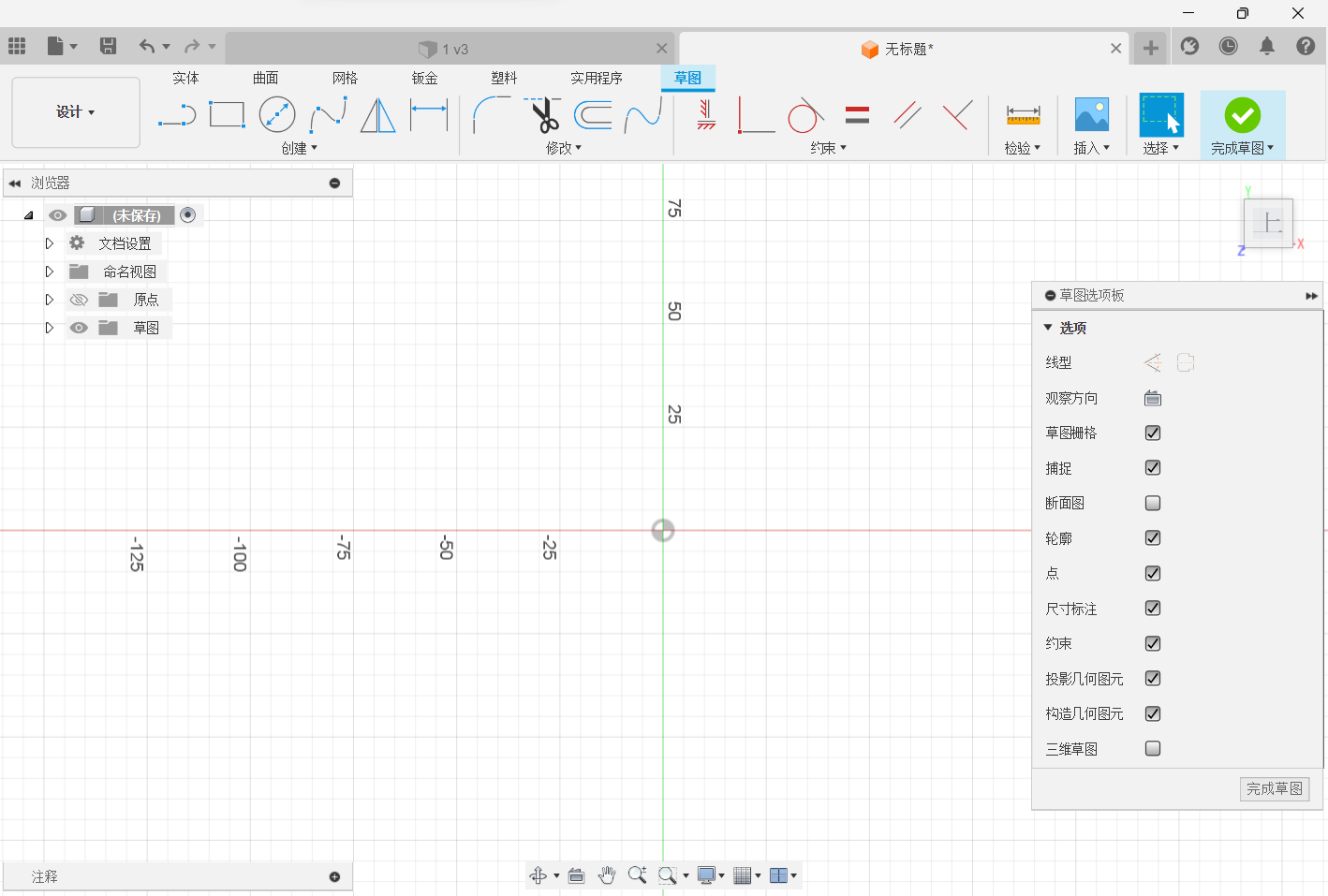
Create a circular sketch from the middle point.
Select sketch size.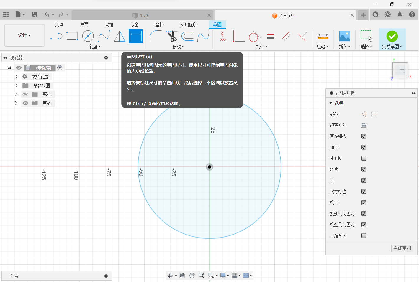
Click the circle to dimension.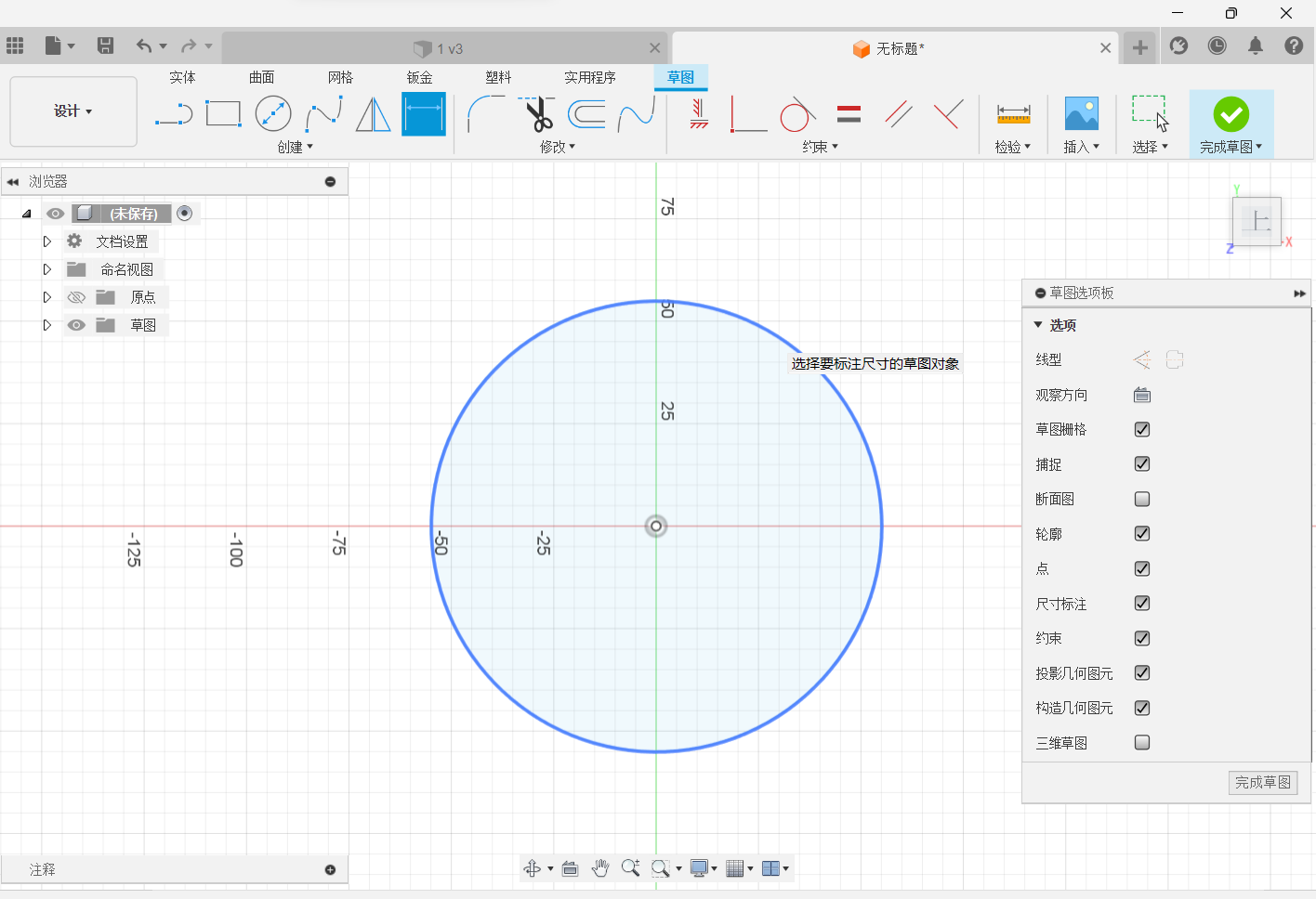
Change the dimension data, and select the OK button.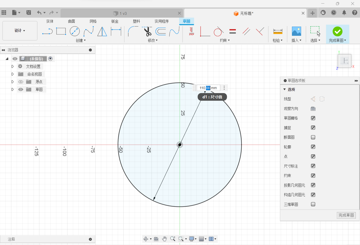
Choose to finish the sketch.
Select a stretch, and drag the arrow to stretch.
Right-hand column changes the data.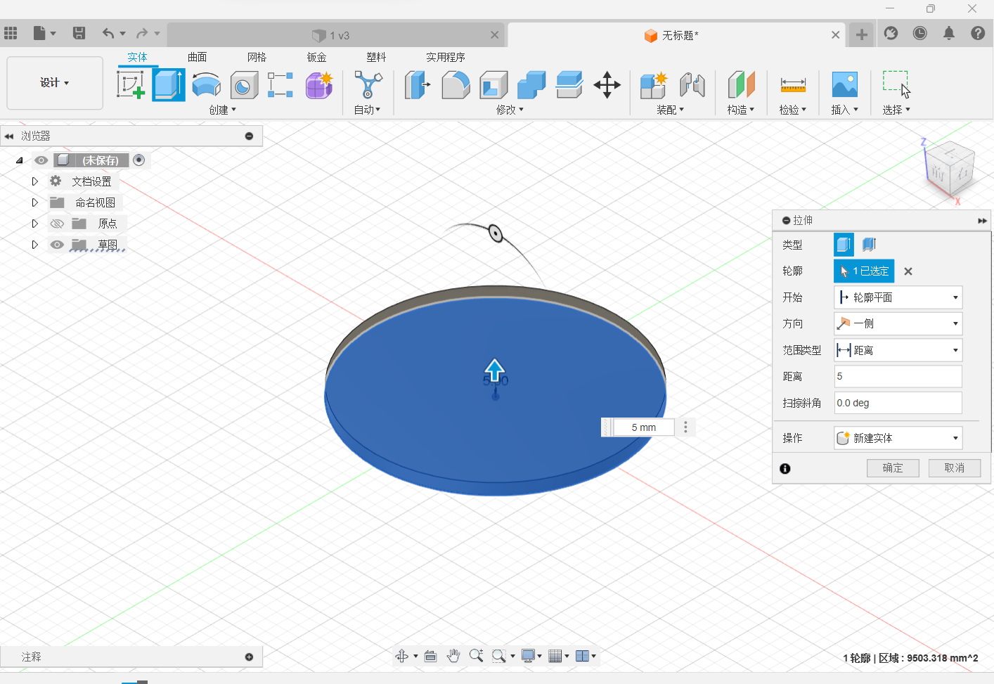
Complete the entity.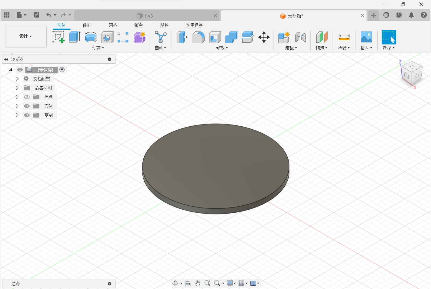
Basic Pendulum Parts Fabrication
Make basic sketches first and determine the size of each dimension of the mechanical structure to prevent the mechanical structure from interfering with each other.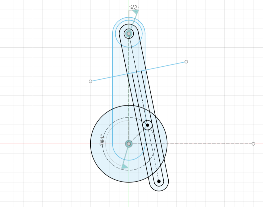
Parameter design practice.
Each size is established in the sketch so that one data adjusts and the rest changes.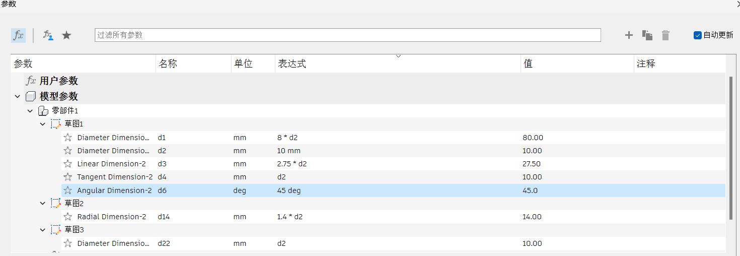
Complete part of the sketch design.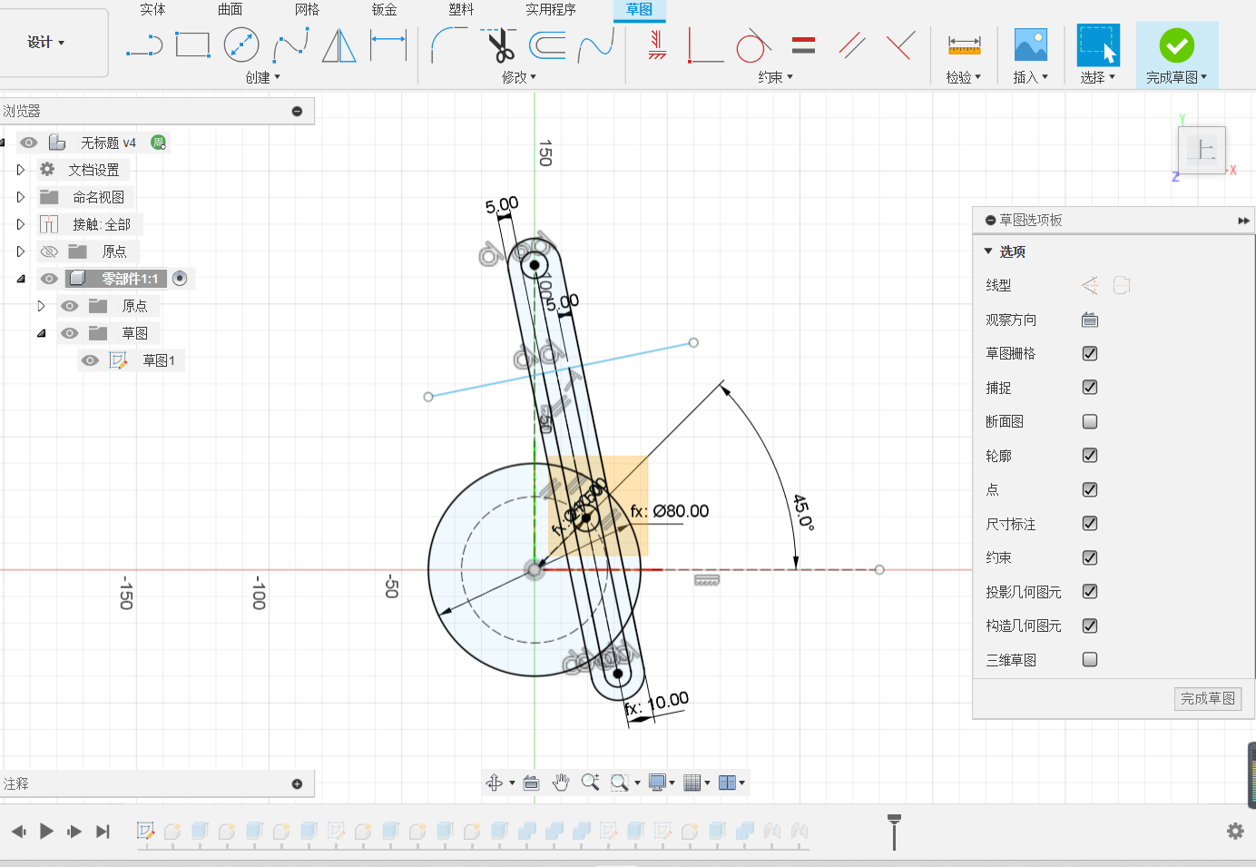
Assembly Task: Assemble The Three Parts in Pairs
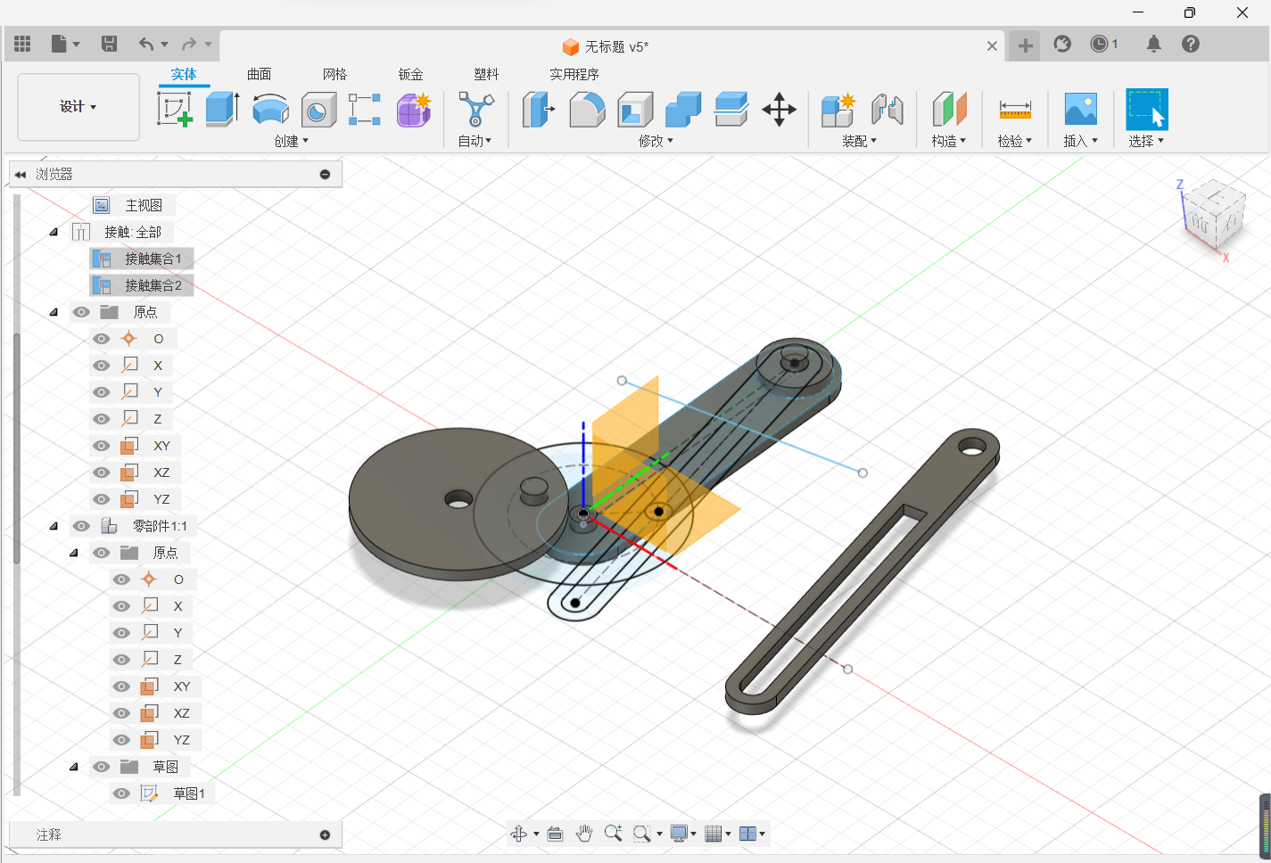
Click [Assembly] and select [Join].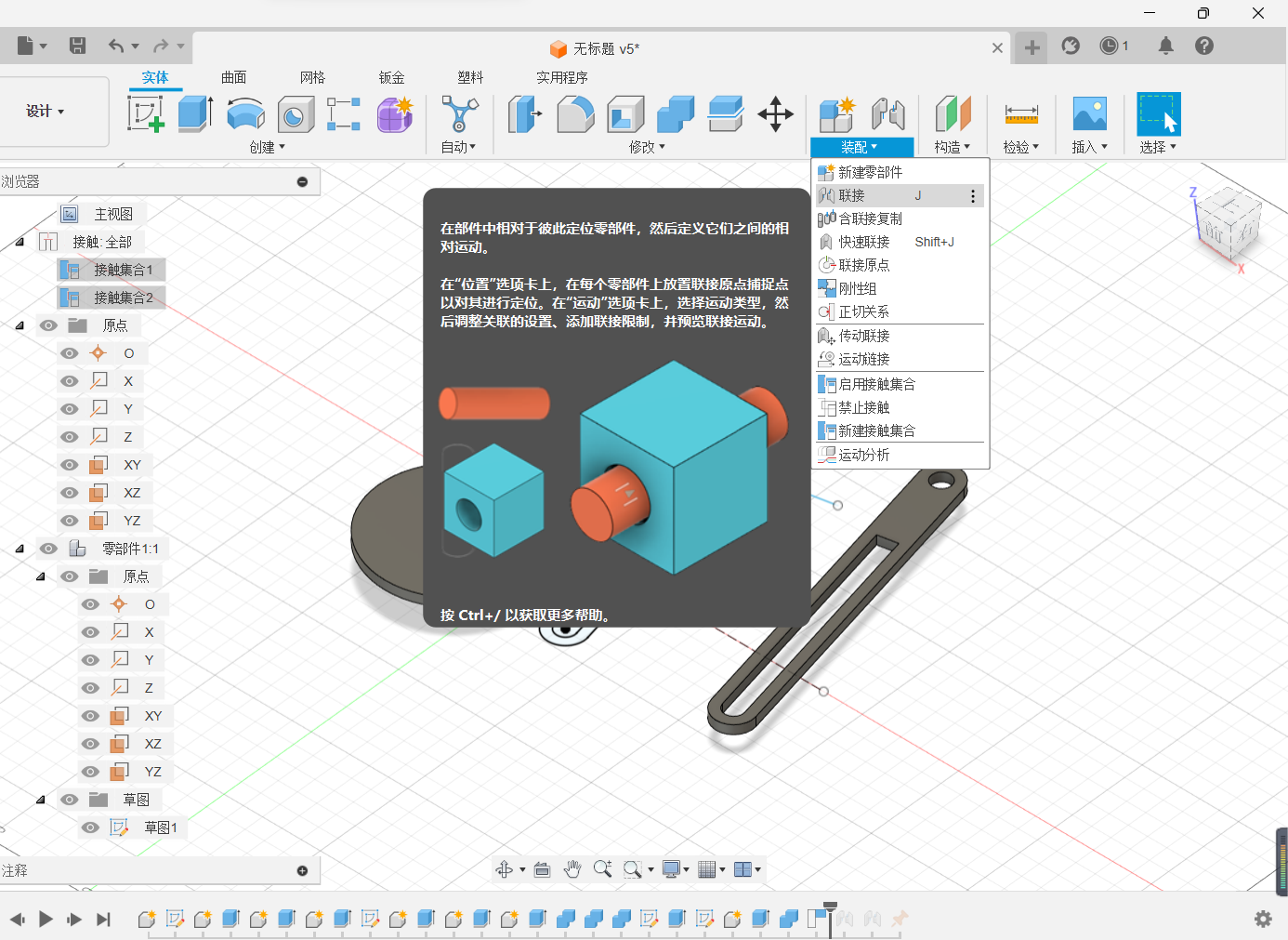
Select the snap point on the two parts that you want to join.
The motion mode of the assembly part is rotation.
Conduct the assembly of two additional components.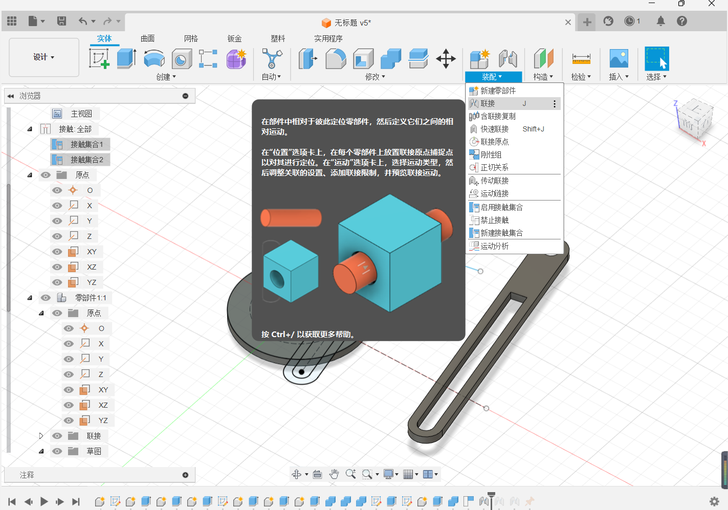
Movement mode or choose rotation.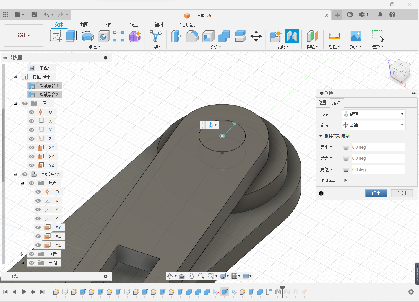
Of the three parts, after the pair has been rotated, enable the contact set to ensure that the small cylinder on one part always slides in the groove and does not penetrate the die.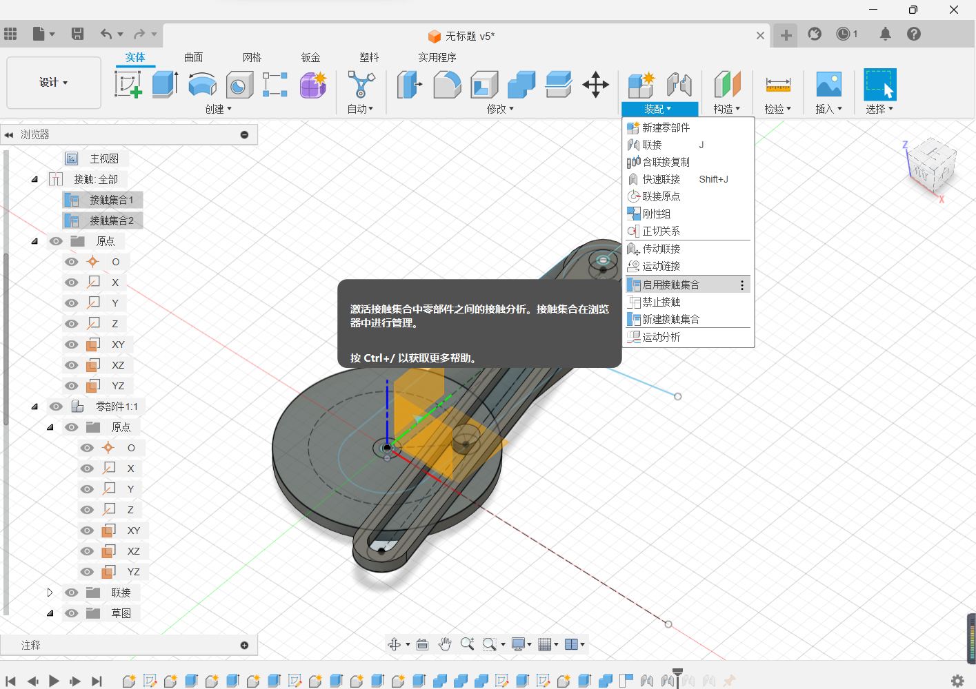
Hold the base and drag the pendulum hammer back and forth.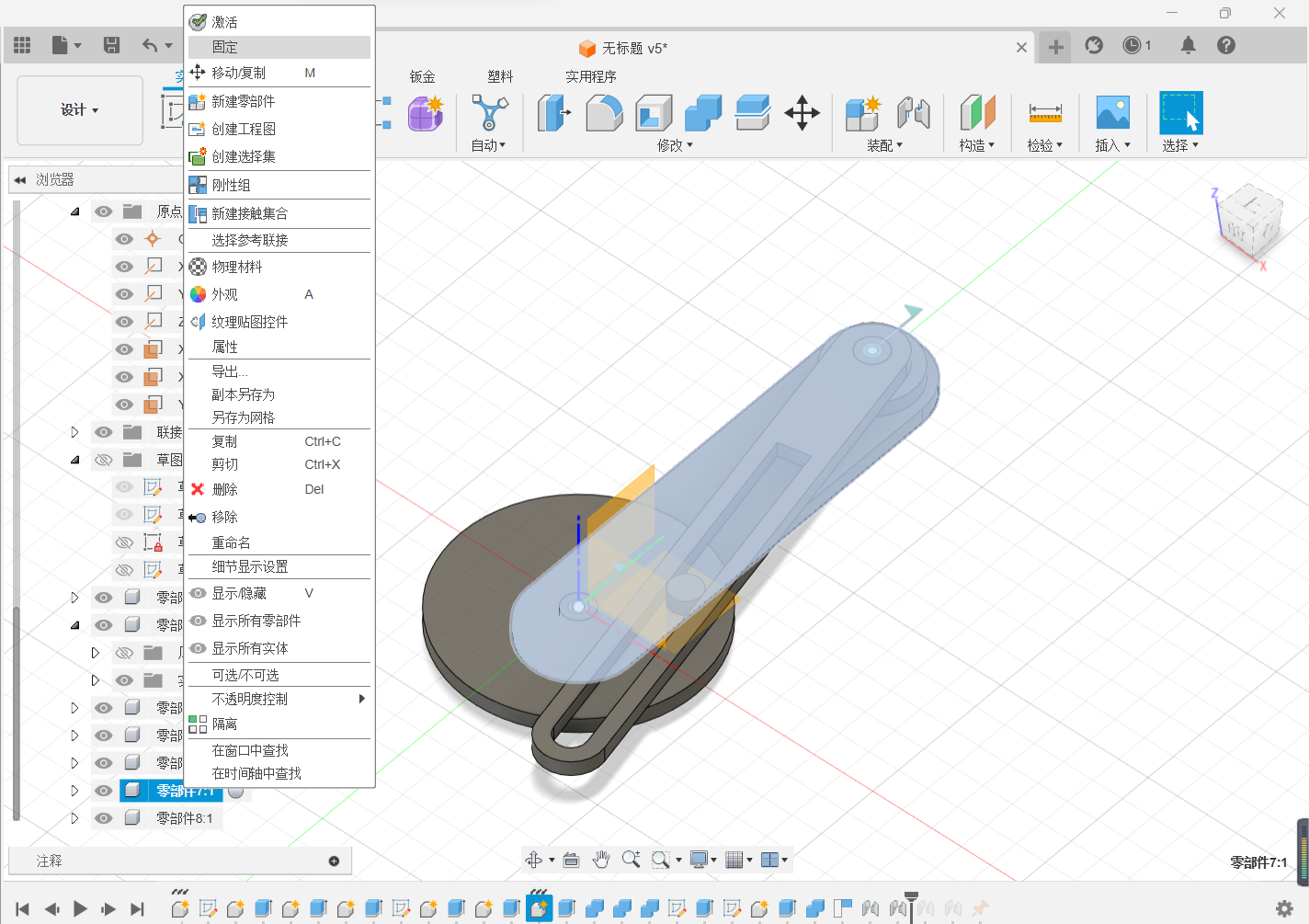
Action connection, which mainly consists of two rotation actions and a contact set.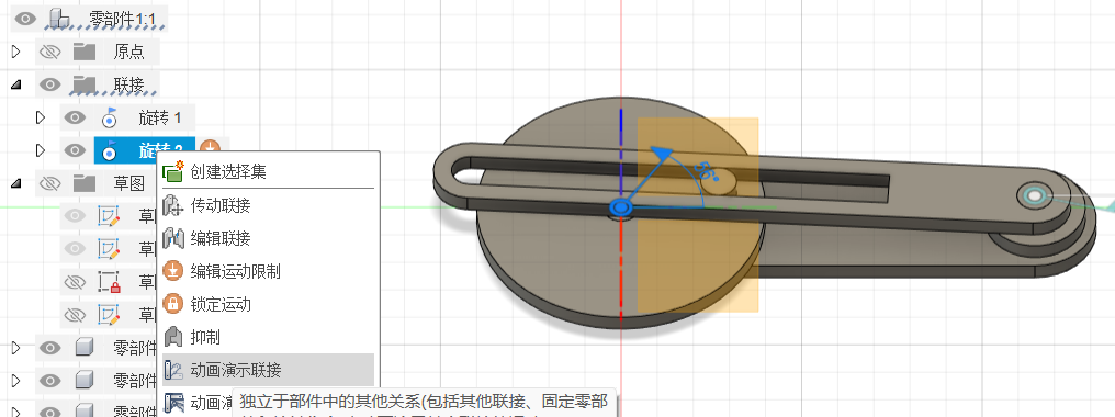

Modeling of Gear Structure Connectors
Tap Utilities–>Additional Modules–>Scripts and Additional Modules (shift+s)–>Additional Modules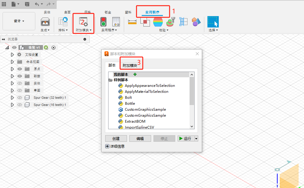
Tap SpurGear–>Run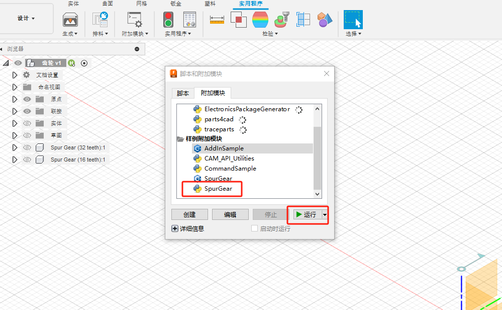
In the entity creation there will be a spurgear icon, click on it –> start adjusting the desired gear parameters.
Successful generation.
Build the gears as described above, making two gears of matching size.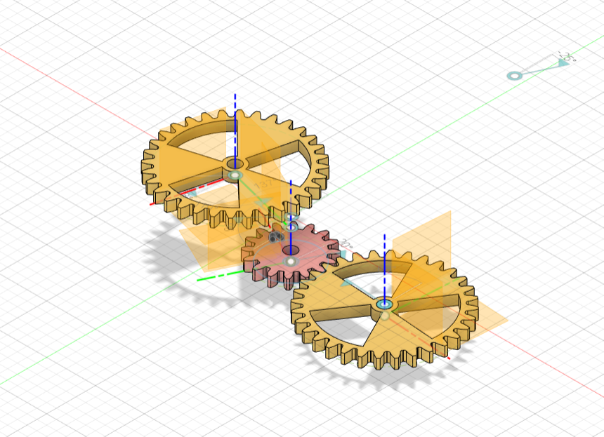
Combine the gear structure with the original large pendulum structure, play a rate adjustment function.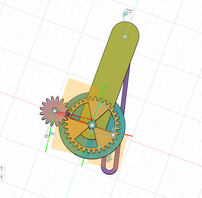
In order to make the human-computer interaction process experience of manipulating the gears better, a small handle with a connection to control the whole mechanism was built at the pinion and some structures were merged.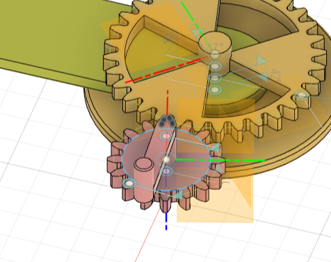
Continue to merge the structure, and made the fixed gears and pendulum connectors, so that the product can be placed on the desktop, the overall reference to the Eiffel Tower angle and shape, as a desktop bye-bye, more stability and a sense of aesthetics.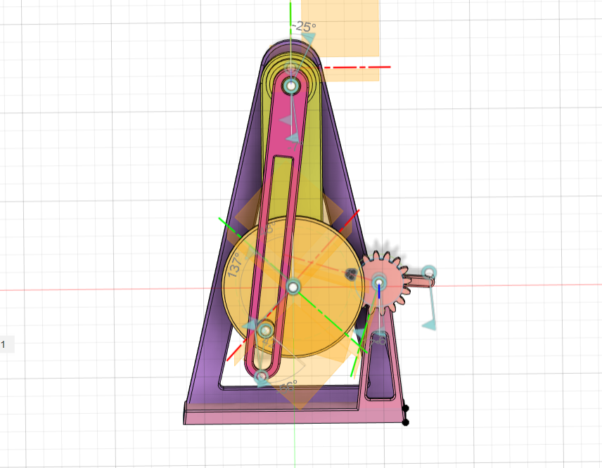
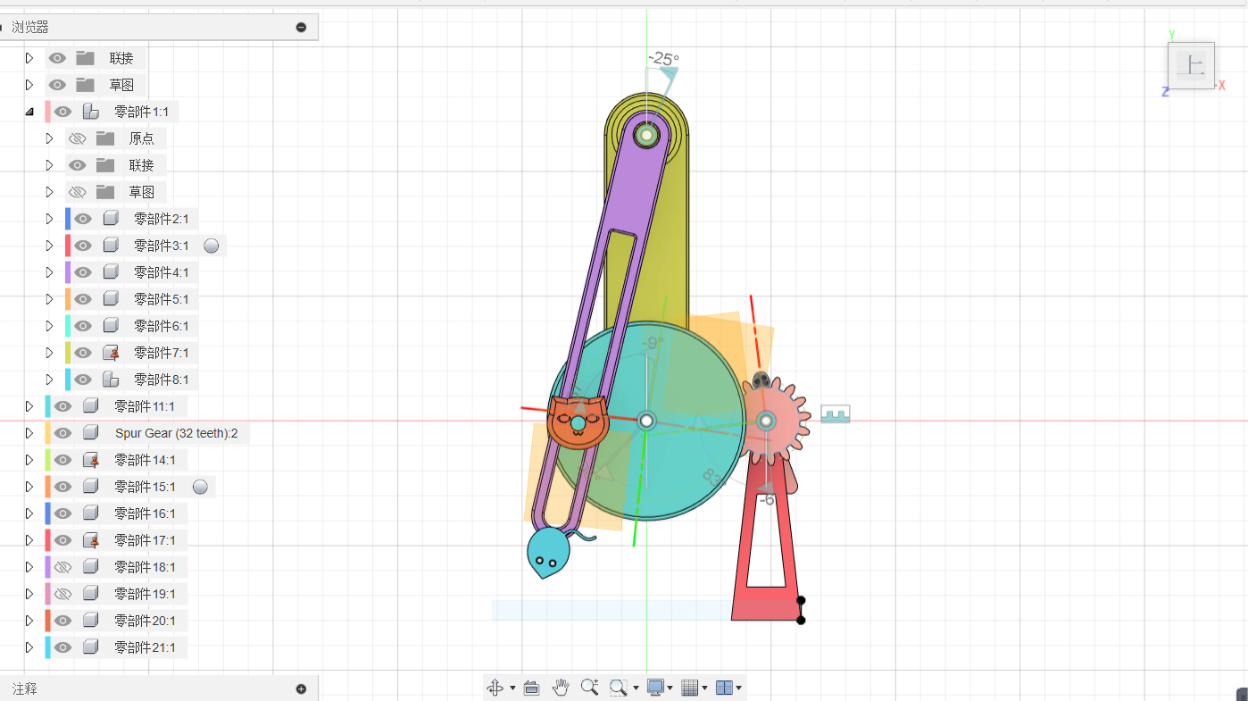
Cat and Mouse Modeling
Sketching a cat and mouse with stretching and fine-tuning of the form.
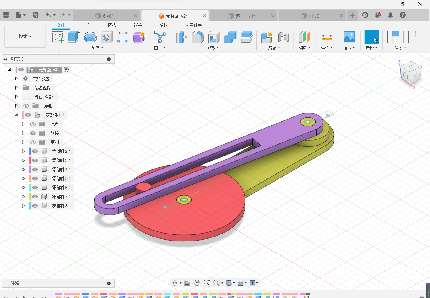
03 Parts Assembly
After opening the contact connection, the contact collection of a part of the components is formulated and assembly actions such as rotation and rigidity are set.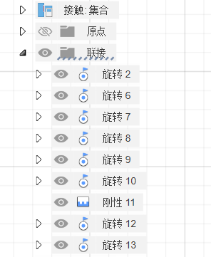
04 Decoration and Beautification
Automated Modeling
Make a sketch with the goal of making a small flower shaped part and use automated modeling.
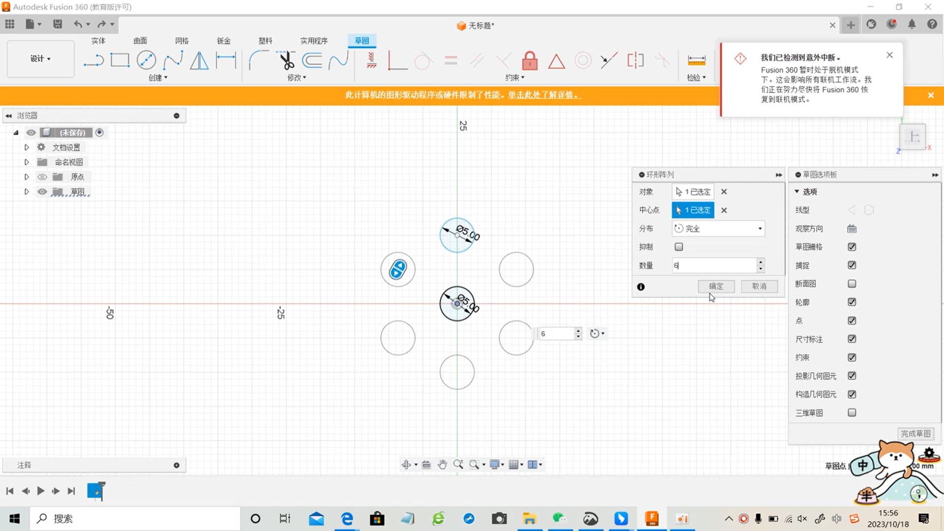
Use the “Ring Array” in the sketch to create a sketch shape.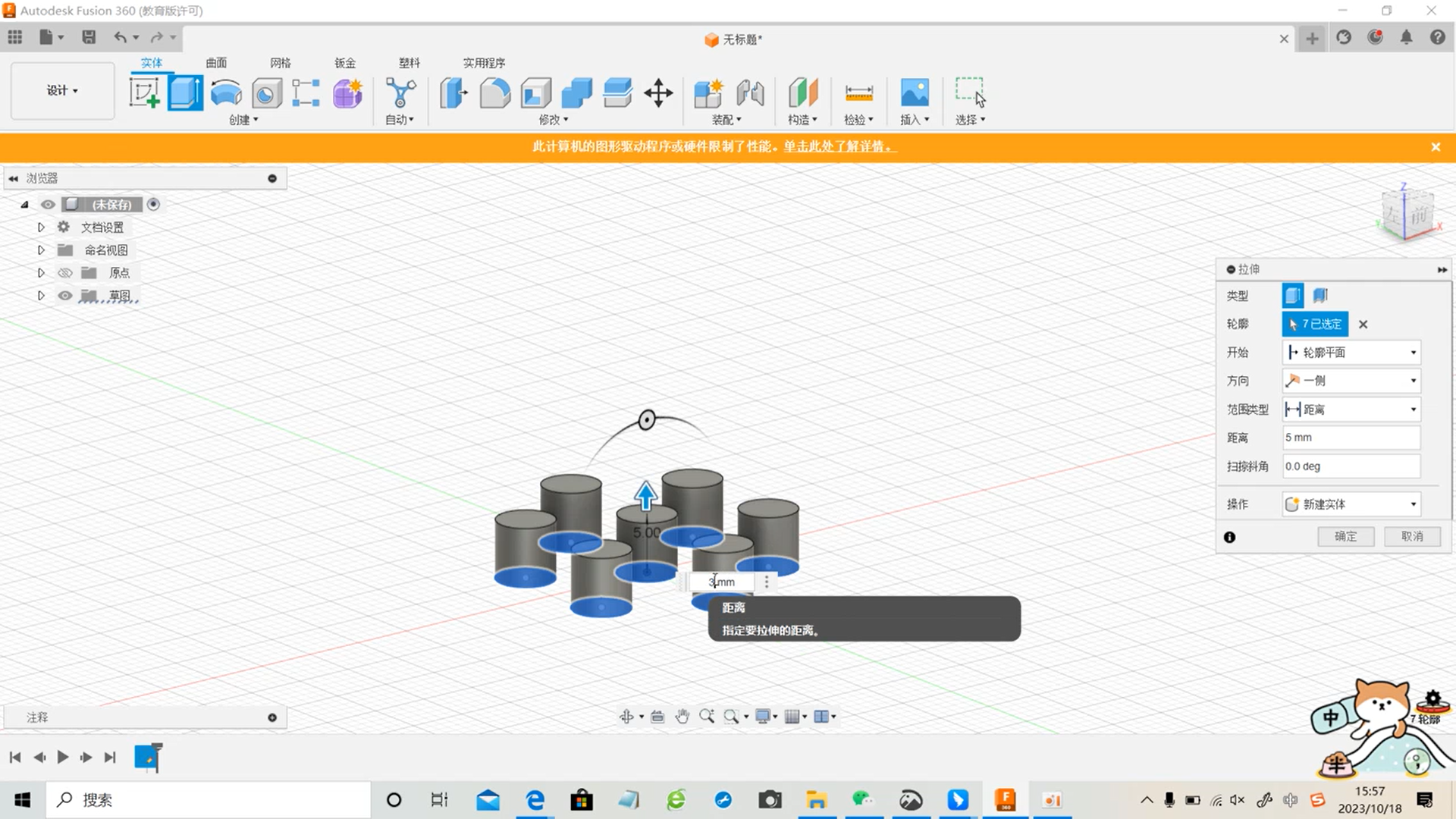
Select the faces to be connected and the entities to be avoided, go through the automated modeling tools and adjust the style and volume of the automated modeling to determine the final modeling.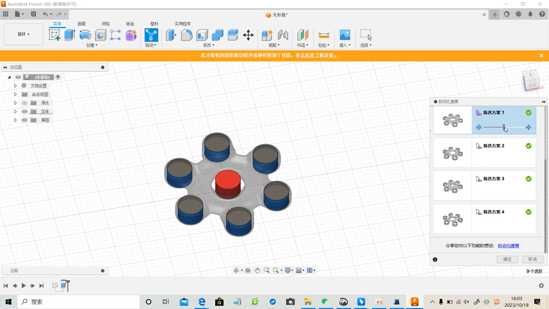
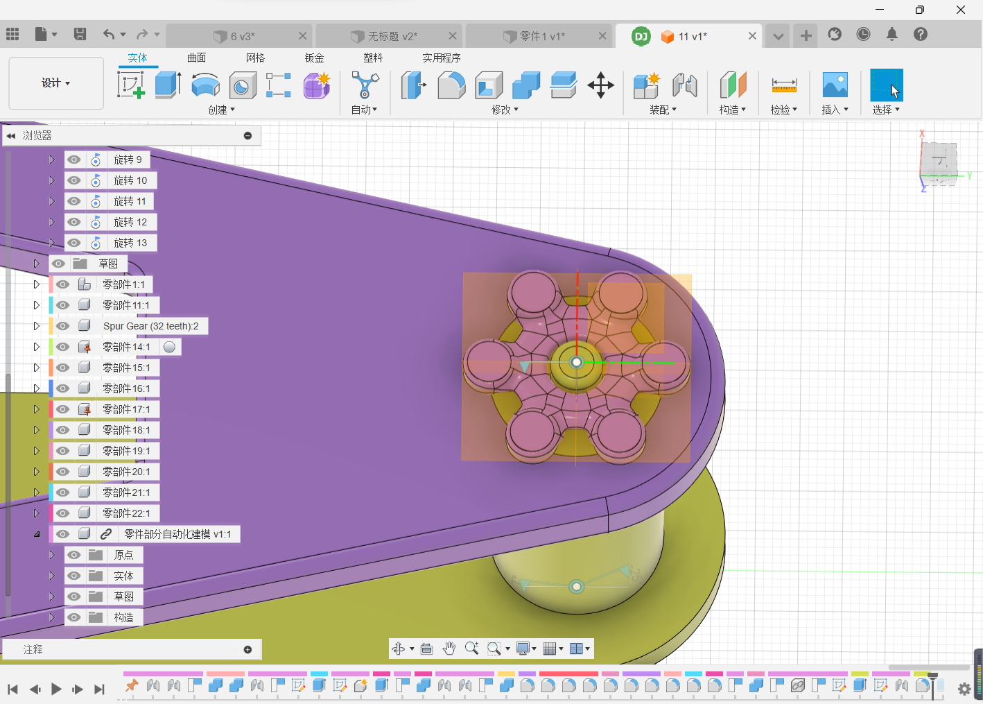
Chamfering and Merging
Click Chamfer, select the edge you want to chamfer and click Finish, the model will be more product-oriented after chamfering.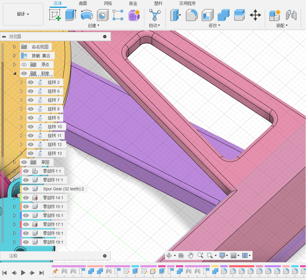
Select the structures that are not interspersed to merge and save the file.
05 Plug-in Use & Model Rendering
Install keyshot and fusion360, facilitate the model to directly export rendering and download the installation package.
Start the installation.
Installation completed.
Click the keyshot icon to go to rendering (rendering a cube as an example).
Successfully access the keyshot rendering interface, you can assign the cube to different materials.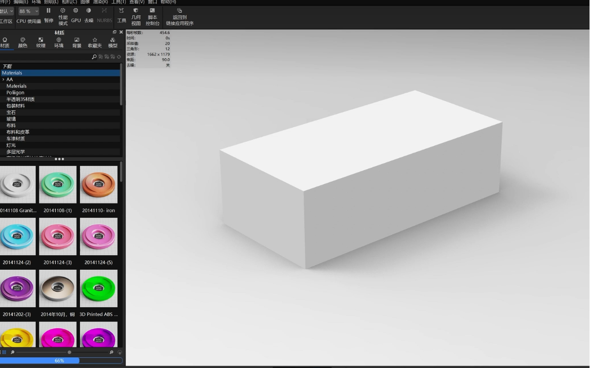
We can then start rendering the product.
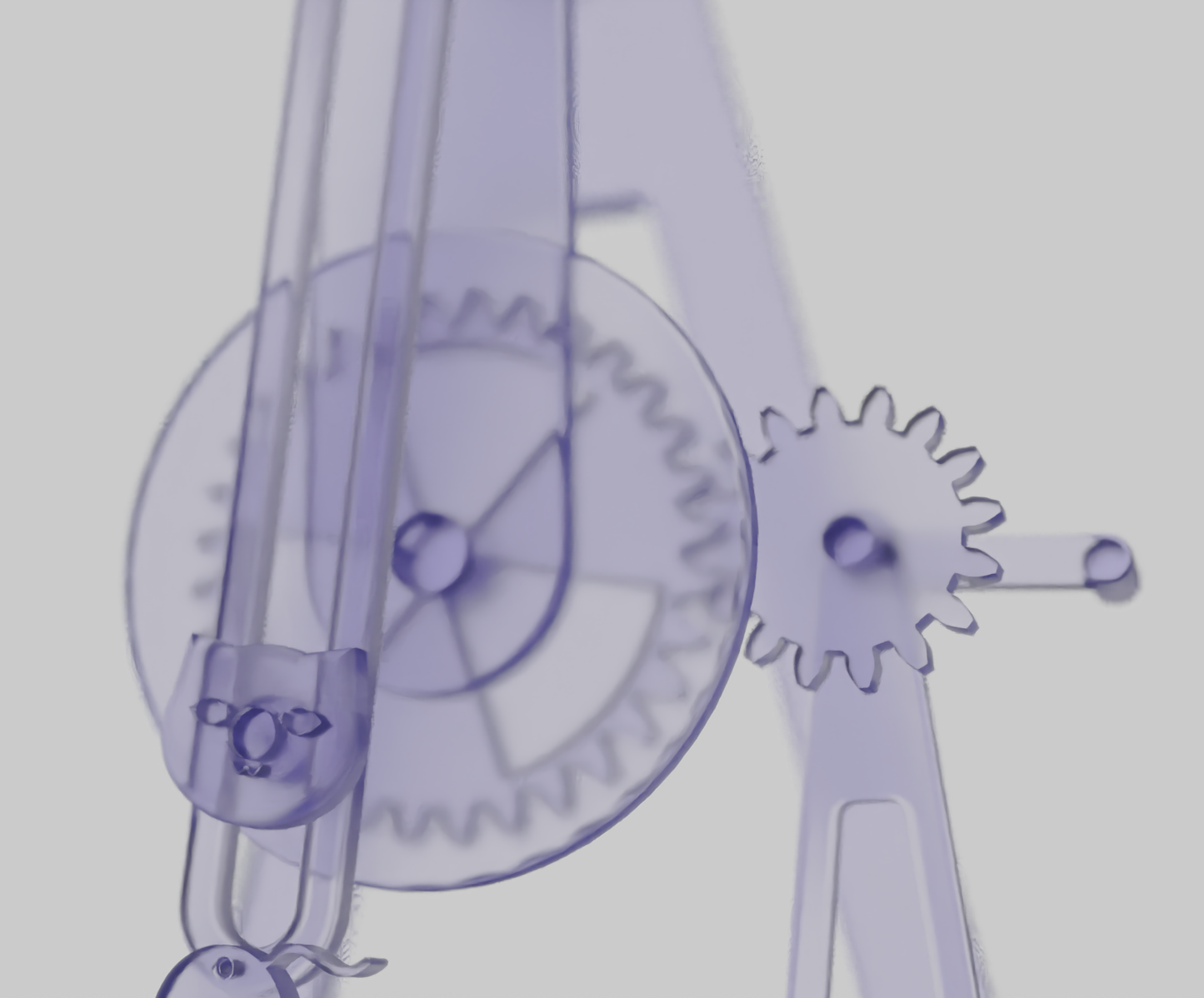
The product rendering and product details are shown below: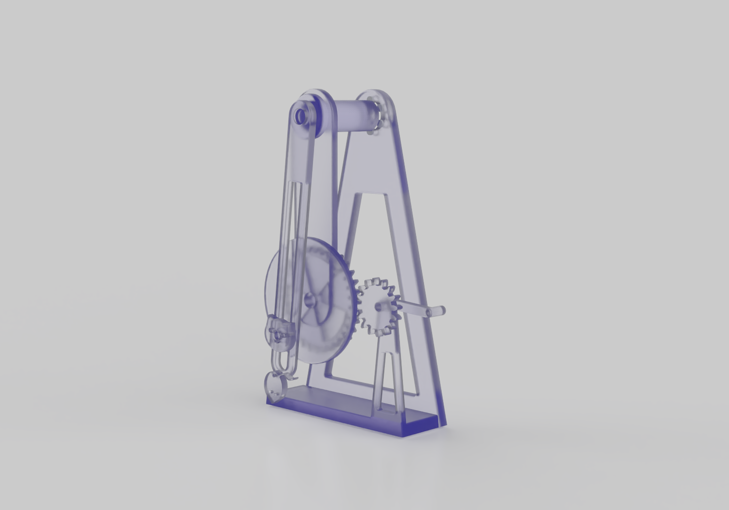
06 Engineering Drawings
Individual Part Engineering Drawing Production
Select [Design] - [Drawing] - [From Design], and build a new drawing.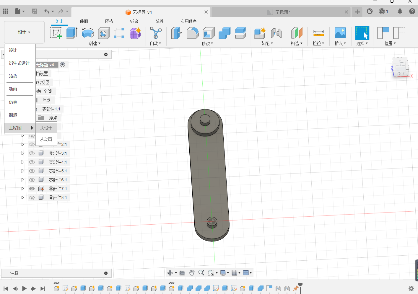
[Create] - [base view], select the proper orientation and style.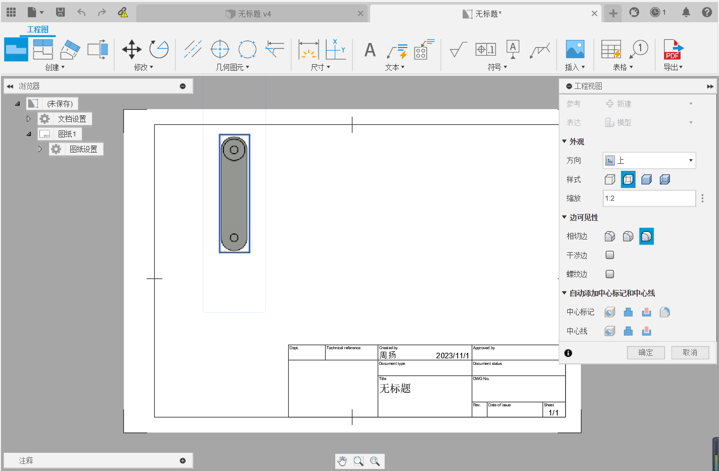
Rotate the view, and move to a reasonable position.
View production completed.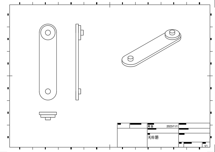
Top left dimension zoom scale.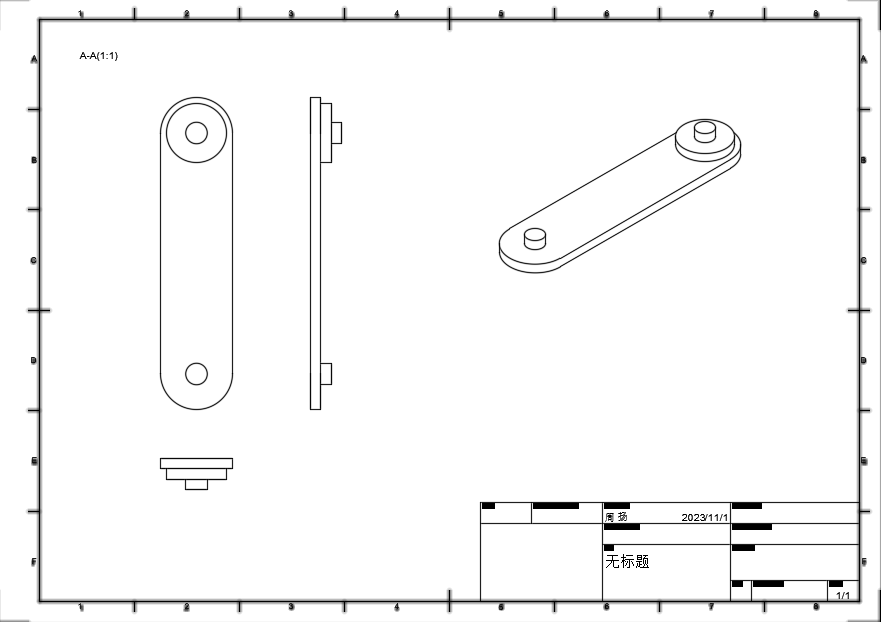
Reasonable dimension labeling, do not repeat, do not omit.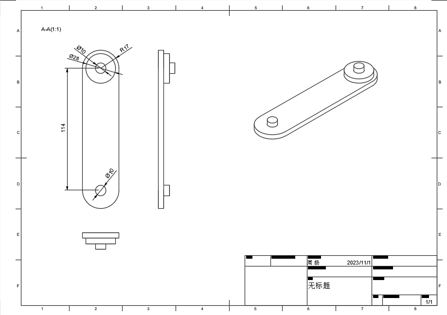
Specify the technical requirements, and complete the engineering drawing.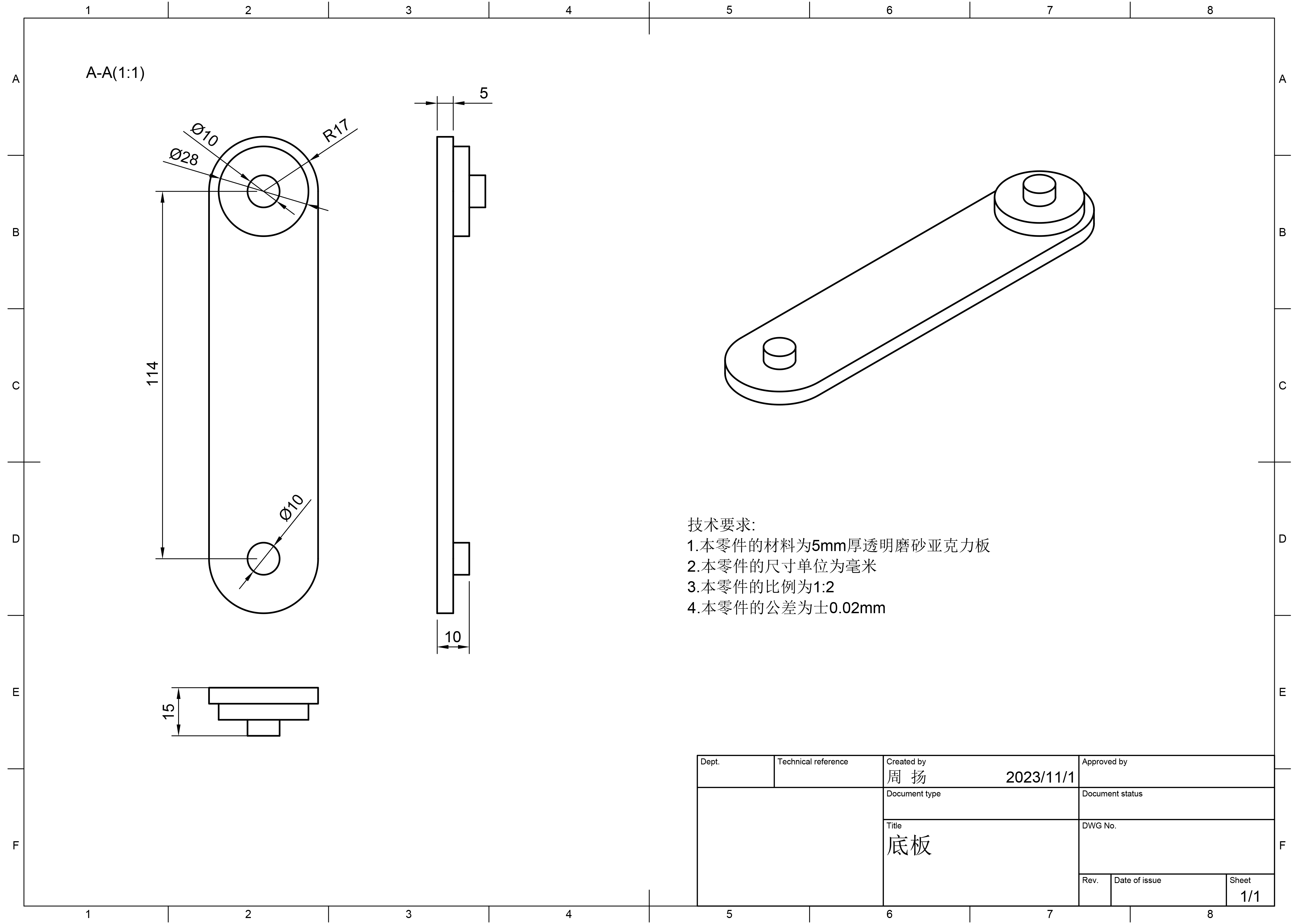
Assembly Engineering Drawing Production
Select [Design] - [Drawing] - [From Design] to create a new drawing.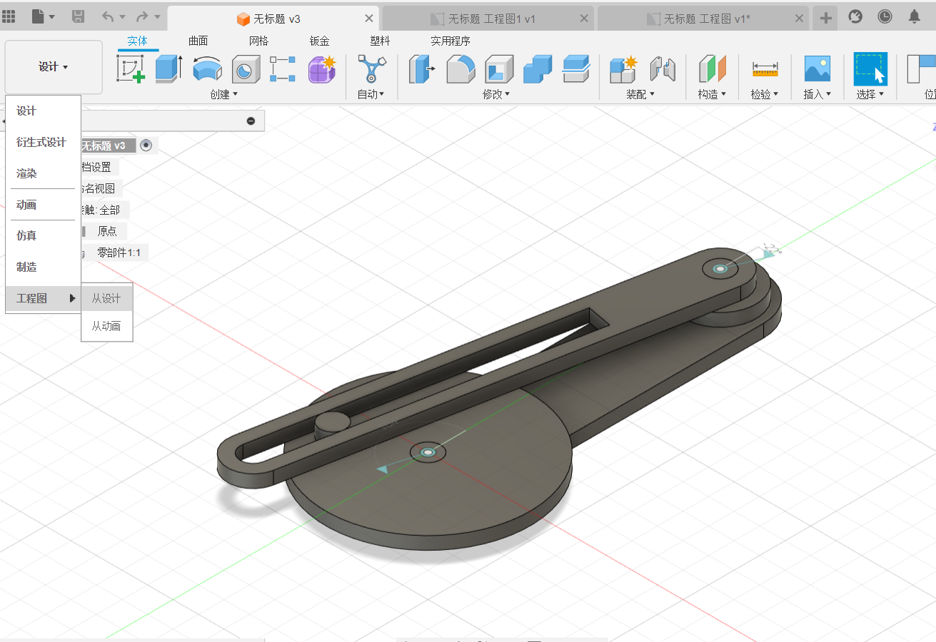
[Create]-[Base View], select a reasonable orientation and style.
Rotate the view and move it to a reasonable position.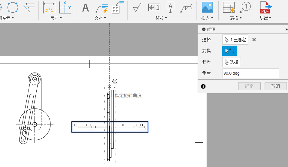
View creation complete.
Zoom ratio is labeled in the upper left corner.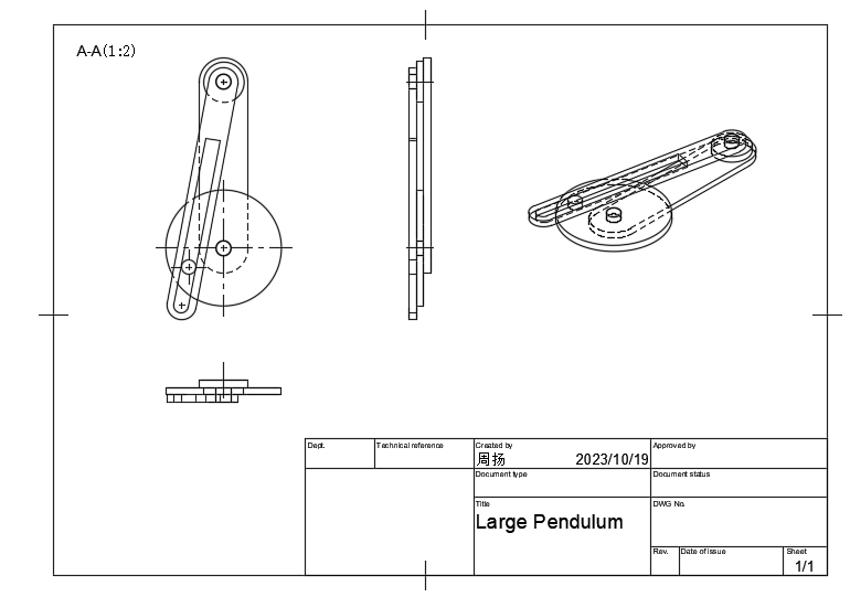
Reasonable labeling of dimensions, so that there is no repetition and no omissions.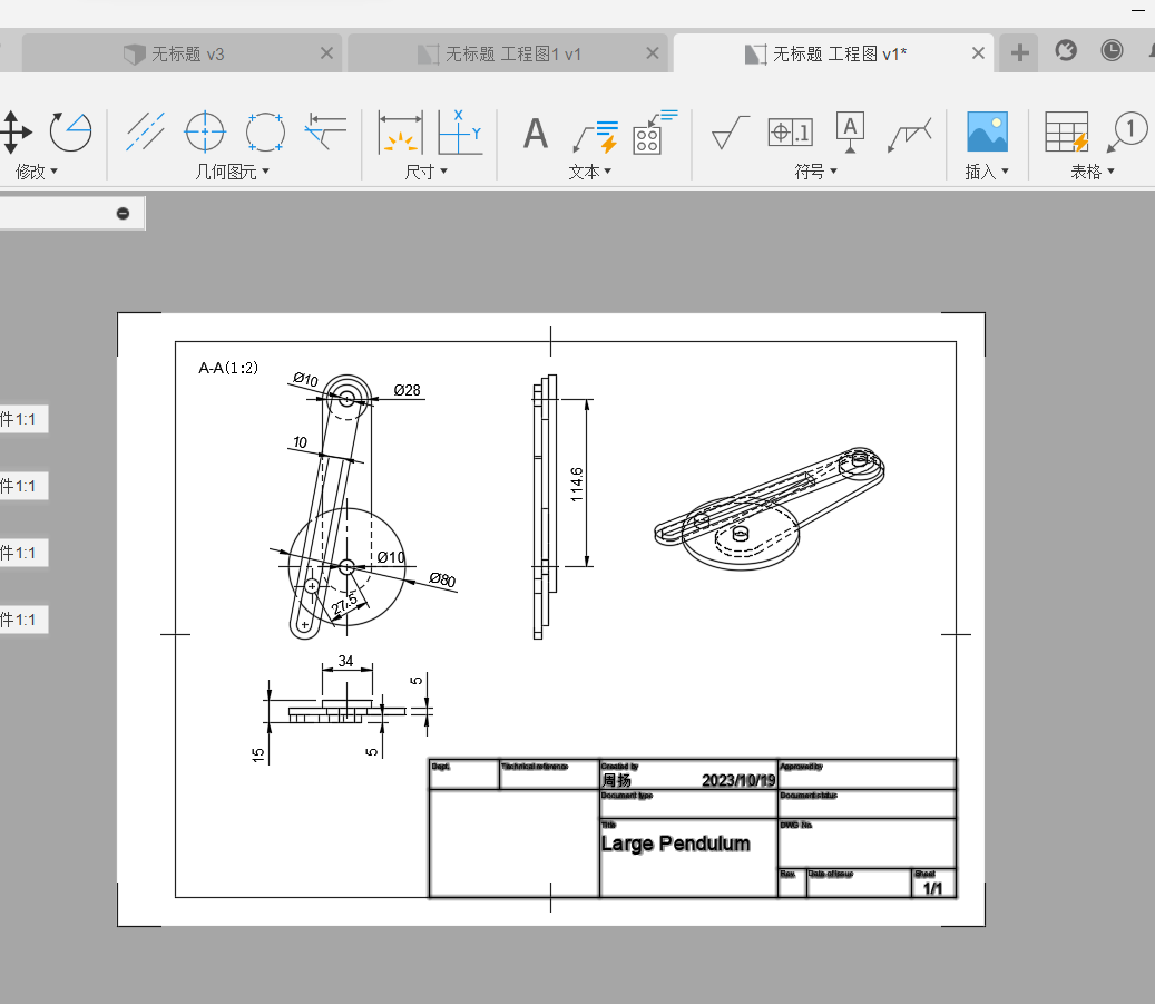
Write technical requirements and complete engineering drawings.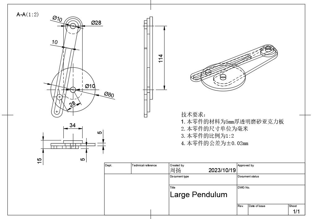
The model is as follows:
Introduction to Creo

01 Software Introduction
Creo software in industrial design modeling in the core concept is from the top to the bottom of the modeling concept and ideas, it is a set of CAD/CAM/CAE in one of the software, especially in the design of product structure, three-dimensional modeling is powerful, full parametric modeling, and, the modeling process is rigorous, the parent-child characteristics of the many, suitable for doing rigorous product structural design, surface modeling is also more convenient, but the shortcomings of the surface quality is not high enough. Its surface modeling is also convenient, but the disadvantage is that the quality of the surface is not high enough, however, it is already capable of handling most of the industries except for the automotive and aerospace industries.CREO is widely used in the industries of home appliances, digital, electronic products, and communication products.
02 Software Origin

03 Areas of Application
Creo as a full range of product design software in the industry enjoys a high reputation, it is widely used in automotive, aerospace, electronics, molds, toys, industrial design and machinery manufacturing and other fields. Especially Creo is a cover conceptual design, 2D design, 3D design, direct modeling and other areas of shared data as well as review the design plan, the function covers the entire product development field, is the current engineering design, product design (appearance), product structural design of one of the widely used software.
Due to Creo’s powerful parametric technology, combined with the top-down Top-Down skeleton modeling idea, it is widely used in product design, R&D design, and can be modified in just a few steps to complete the purpose of changing the product model.
04 Functional Module
| NAME | SOFTWARE | INTRODUCTION |
| Creo | Creo Parametric | Create 3D designs using powerful, adaptive 3D parametric modeling techniques |
| Creo Simulate | Analyze structural and thermal properties | |
| Creo Direct | Create and edit 3D geometry using fast and flexible direct modeling techniques | |
| Creo Sketch | Easily create 2D hand-drawn sketches | |
| Creo Layout | Easily create 2D conceptual engineering design plans | |
| Creo View | Creo View MCAD | Visualize mechanical CAD information for faster design review |
| Creo View ECAD | Quickly view and analyze ECAD information | |
| Creo Schematics | Create 2D wiring diagrams for duct and cable system designs | |
| Creo Illustrate | Reuse 3D CAD data to generate rich, interactive 3D technical illustrations | |
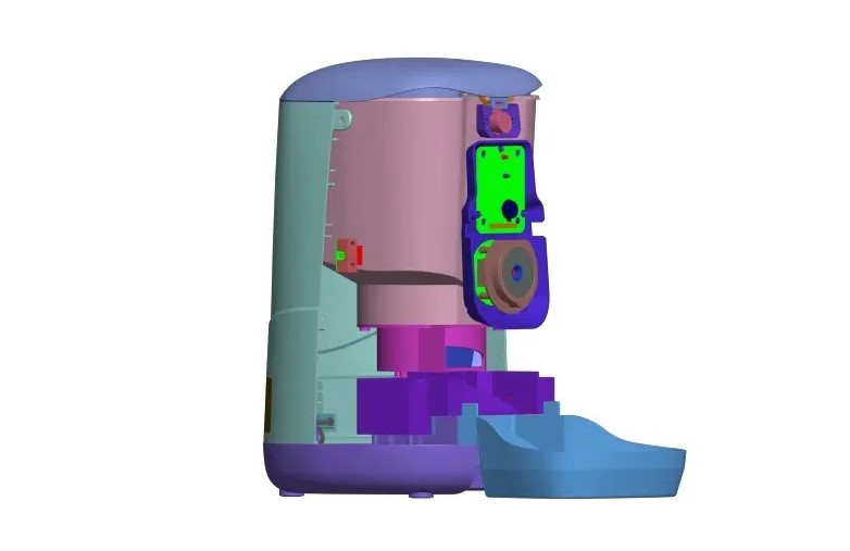
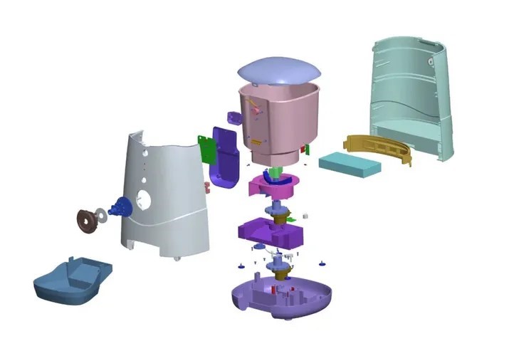
05 Case Studies
The following images roughly show a model of a pet feeder product designed and manufactured using Creo.

Introduction to Solidworks

01 Software Introduction
SolidWorks (stylized as SOLIDWORKS) is a brand within Dassault Systèmes that develops and markets solid modeling computer-aided design, computer-aided engineering, 3D CAD design an collaboration, analysis, and product data management software.
02 Software Origin
The SolidWorks brand was founded as Winchester Design Systems by Massachusetts Institute of Technology graduate Jon Hirschtick on December 30, 1993. Jon and cofounders Dr. Constantine Dokos, Scott Harris, Bob Zuffante, Mike Payne, and Tommy Li aimed to create 3D design software that was affordable, easy to use, and available on a Windows NT personal computer.
SolidWorks developed the world’s first 3D CAD solution that ran on a desktop PC. They had a simple mission statement of “3D on every engineer’s desktop.
SolidWorks released its first product, SolidWorks 95, on November 1, 1995. Within two months, it established a new benchmark for ease of use. Since then, the 3D CAD product, now known as SolidWorks, has become the flagship product for the SolidWorks brand.
By 2023, approximately 7 million engineers and designers were using SolidWorks software to create production-ready 2D and 3D engineering drawings and advanced 3D models using a parametric feature-based approach. SolidWorks also gives users the ability to perform analyses and simulations, including Finite Element Analysis. The product places an emphasis on faster modeling, new design tools, and enhanced collaboration.
03 Areas of Application
The SolidWorks’s user base ranges from individuals to large corporations and covers a wide cross-section of manufacturing market segments. Its core industries include industrial equipment, high-tech, life sciences, and home and lifestyle, and architecture, engineering, and construction. Commercial sales go through an indirect channel that consists of 500+ partner resellers throughout the world. SolidWorks also partners with third-party developers to add functionality in niche market applications such as circuit layout and tolerance checking.
Directly competitive products to SolidWorks 3D CAD include PTC Creo Elements/Pro, Solid Edge, and Autodesk Inventor.
04 Functional Module
- SolidWorks is a 3D CAD software that uses a feature-based approach. It’s equipped with the Parasolid modeling kernel.
- Parameters define the shape of a model or assembly and can be numeric or geometric, linked via relations.
- Design intent determines how a part responds to changes. For instance, SolidWorks allows users to specify the hole’s position regardless of can size.
- Features are the building blocks of parts, either shape-based (using sketches) or operation-based (e.g., fillets, chamfers).
- Modeling typically begins with a 2D sketch, where geometry, dimensions, and relations drive design intent.
- In assemblies, mates serve the role of sketch relations, aiding in component alignment.
7.Drawings are created from parts or assemblies, with automated views and easy addition of notes and dimensions. Various paper sizes and standards are supported.
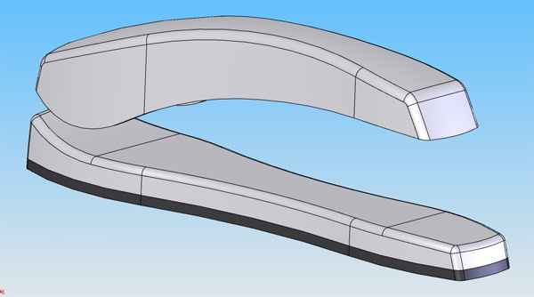
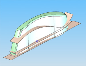
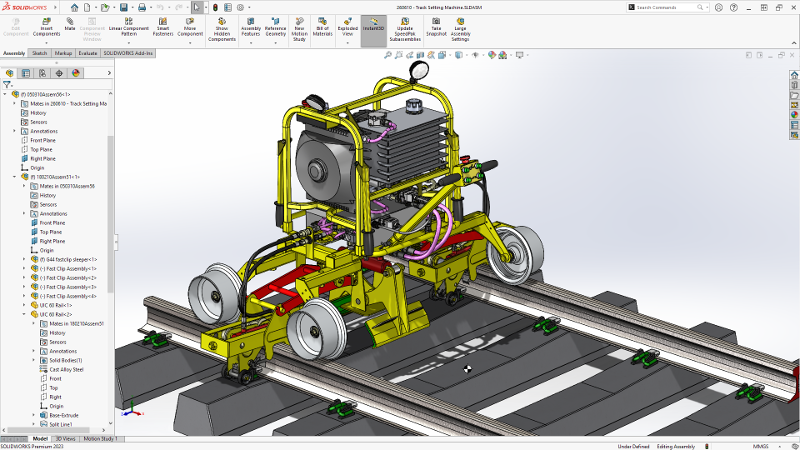
05 Case Studies
The following images roughly show a model of a pet feeder product designed and manufactured using Solidworks.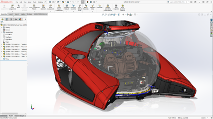

Comparison of Creo and Solidworks

01 Common
In-memory Parts Management
Creo, Solidworks cannot close files in memory individually.
Edits to Non-Participating Entities
Creo edits non-parametric models through Flexiable modeling. When importing a multi-solid non-reference model, it is slightly more complicated to edit it with Creo.
Solidworks edits the model by directly editing the move/rotate/copy commands, but each step is recorded in the model tree and cannot be de-referenced.
Part Assembly and Movement
Core parts are relatively difficult to move accurately.
Solidworks can only move accurately through the assembly within the assembly.
Multi-Solid Modeling, Welding and Cutting Iists
SW multi-substance modeling, complete the skeleton line design, using a defined sketch section, you can easily scan to generate multi-substance models, and through the welding cutting list to easily generate engineering drawing details. This function SW is the most powerful and convenient.
Shortcut Key
Creo uses mapkey mapping definitions to define two or more combinations of keyboard letters.
Part Templates, Drawing Templates, etc.
SW template settings are more convenient, in the preferences settings, select the path where the modified file is located, you can easily set up, part templates, engineering drawing templates, detail table templates, cutting list templates.
Creo through the config.pro file to set the template folder path.
02 3D Modeling
Top Down
Creo uses a skeleton model, copying geometry and publishing geometry to complete top-down modeling, and the main geometric features exist in the skeleton model.
Solidwork top-down modeling, in the parts directly refer to each other, when the reference data is more, and there is a constraint assembly relationship between the parts, the change is more complex, the model is prone to error.
Line Segment Midpoint Selection and Constraints
Creo, SW is unable to select the midpoint of a line segment, and perform midpoint constraints.
Hole Feature Creation
Creo locates holes in both directions and creates groups of holes through arrays.
Solidworks defines hole types and hole positioning through “Simple Hole” and “Shaped Hole Wizard” respectively.
Center Constraints
This assembly constraint is not available in Creo; it is available in Solidworks using the advanced assembly “width”.
03 Engineering Graphics
Drawing Files and 3D Model Files
Solidworks, engineering drawings and 3D model is the same part number, you can realize the virtual background, but the structure of the main model is bloated and complex, large assembly components will reduce the speed of the computer.
Creo, similar to Solidworks, can not insert another part in the drawing file to realize the virtual background.
Weld Marking
Solidwork labeling is easier.
Creo weld labeling is very cumbersome, different types of weld labeling by a different symbol to achieve.
Reference
https://www.nexmaker.com/doc/2cad/Fusion360prepare.html
https://www.bilibili.com/video/BV1Sg411m72z
https://b23.tv/QML03s3
https://www.bilibili.com/video/BV1FA411M7VN/?vd_source=ba7dc2f33aa076b749012d4df45343cc
https://zhuanlan.zhihu.com/p/607367731?utm_id=0
https://baike.baidu.com/item/creo/6642952?fr=ge_ala
https://zhuanlan.zhihu.com/p/570622717
https://en.wikipedia.org/wiki/SolidWorks#
https://en.wikipedia.org/wiki/Comparison_of_computer-aided_design_software