Processing with Arduino
Connecting Processing with Arduino to Control RGB LED
In this design, the color ratio of the three blocks - red, green, and blue - will be controlled in Processing. The corresponding color ratios will be input into the RGB LED, causing it to display the corresponding colors.
Hardware Usage and Connection
- RGB LED
The RGB LED is composed of red, green, and blue light mixed together. The maximum brightness value for each color is 255. By changing the mixing ratio of the three colors, many different colors can be obtained. Among the four pins of the RGB LED, three pins correspond to the red, green, and blue pins respectively, while the other pin is usually the VCC (Anode) or GND (Cathode) pin. The common cathode RGB LED is used in this experiment.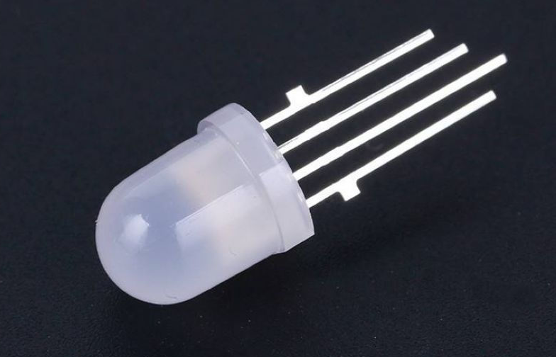
- Hardware Connection
This hardware setup uses an Arduino Uno, an RGB LED, a breadboard, three 220-ohm resistors, and several wires. The circuit diagram is shown below: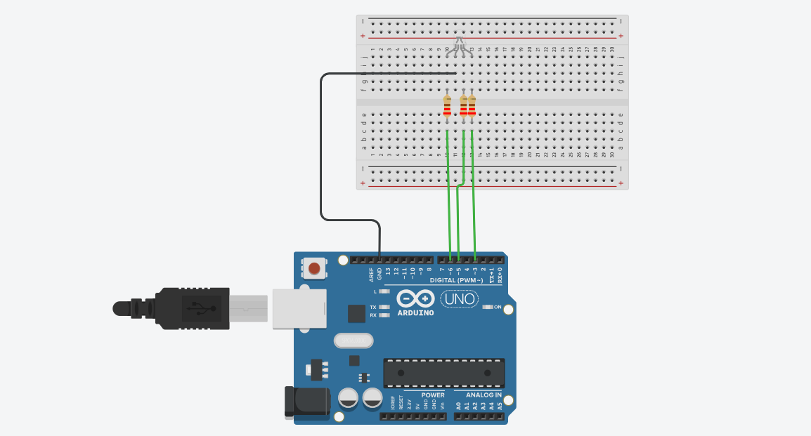
Connecting Processing with Arduino
- Relevant Settings in Processing
Processing can be connected to Arduino to achieve bidirectional communication between the two. In this experiment, we will first draw the red, green, and blue color blocks in Processing, and control the RGB LED to emit the corresponding color light by adjusting the mixing ratio of the three colors. To connect Processing with Arduino, you must choose the correct port in Processing and make a declaration.
First, determine the port of the connected Arduino board. We are using the “COM5” port here, as shown in the figure: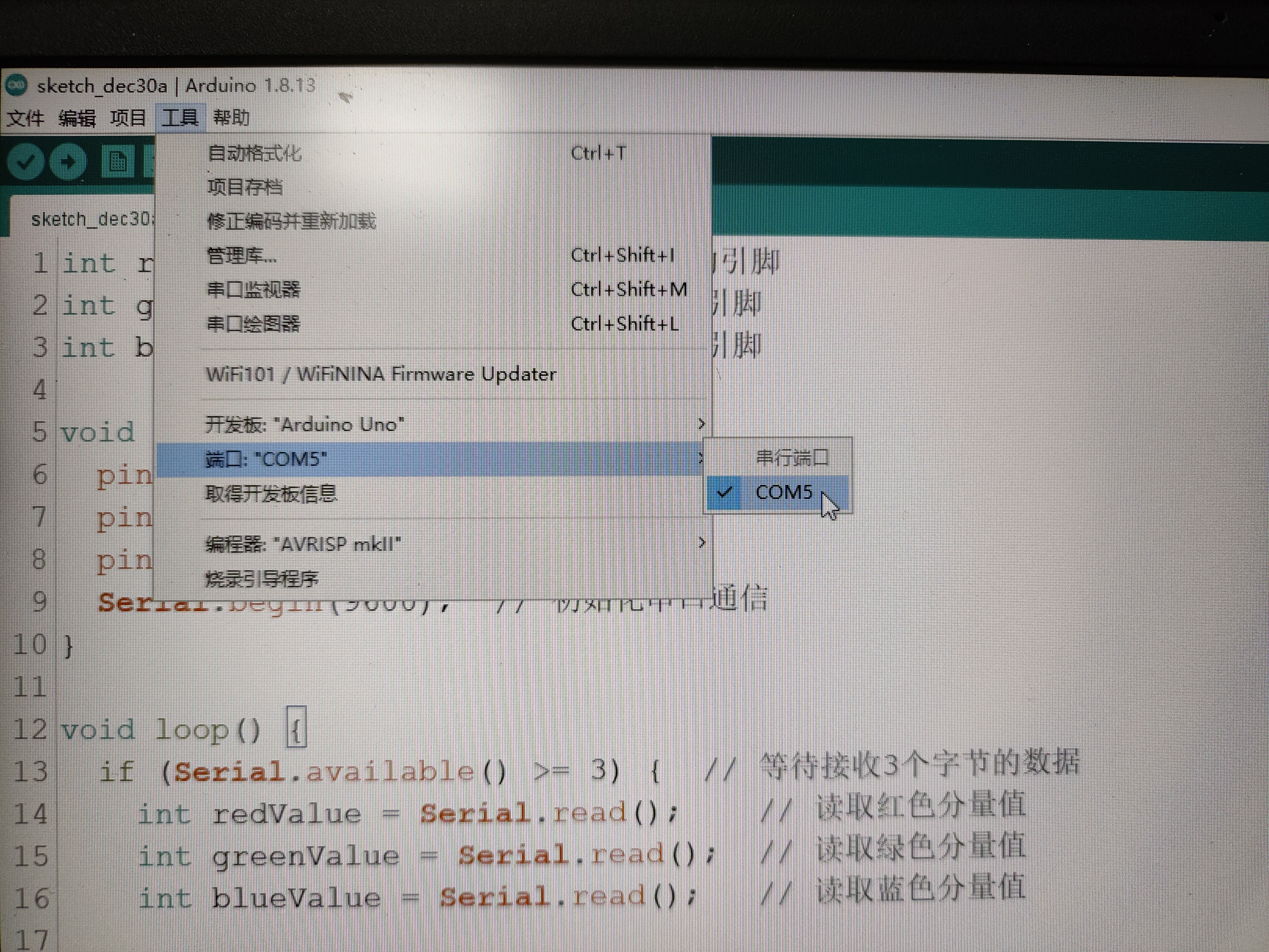
The code required for connecting Processing with Arduino is shown below: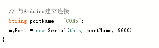
- Processing Code
We drew the red, green, and blue color blocks in Processing and by adjusting the proportions of each block, you can see the mixed color in the lower square block. The Processing code is shown below:
1 | |
- Arduino Code
After connecting Processing with Arduino and connecting the RGB LED to the respective pins, you can adjust the color of the RGB LED. The Arduino code is shown below:
1 | |
After compiling the code in both Processing and Arduino, you can click “run” in Processing to start the program, as shown in the figure: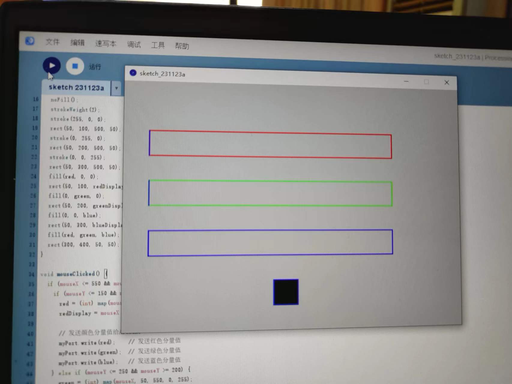
Demonstration
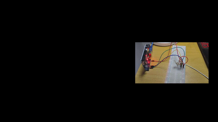
The following figure shows the actual demonstration of the RGB LED changing its color based on the color ratio adjustment in Processing. By adjusting the corresponding ratio, different colors can be displayed.
Reference article link for this section:
RGB LED:https://blog.csdn.net/weixin_41659040/article/details/104854670