ArduinoIO
1 Potentiometer Control Servo Rotation Angle
This experiment combines a potentiometer with a servo motor, using the potentiometer to control the servo motor. The servo motor rotates to the corresponding angle as the potentiometer knob is turned.
Hardware Connection
- Potentiometer:
The potentiometer is a non-polar device and a type of variable resistor. It has three terminals, and by rotating the knob, the position of terminal 2 changes, which in turn changes the resistance value. Terminal 1 is connected to the 5V pin of the development board, terminal 3 is connected to the GND pin, and terminal 2 is connected to an analog input pin.
The connection of the potentiometer’s three terminals is shown below: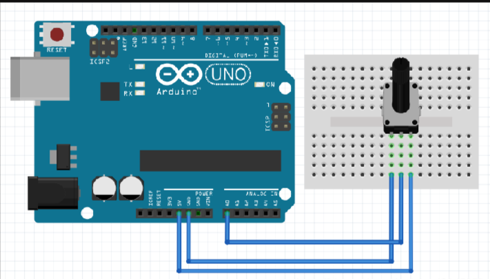
- Servo Motor
(1) The SG90 servo motor is a position (angle) servo driver, suitable for control systems that require continuous and controllable angle changes. In robot mechatronic control systems, servo motor performance is an important influencing factor. Servo motors can be used as basic output actuators in micro-electromechanical systems (MEMS) and aero modeling, and their simple control and output make it easy to interface with microcontroller systems.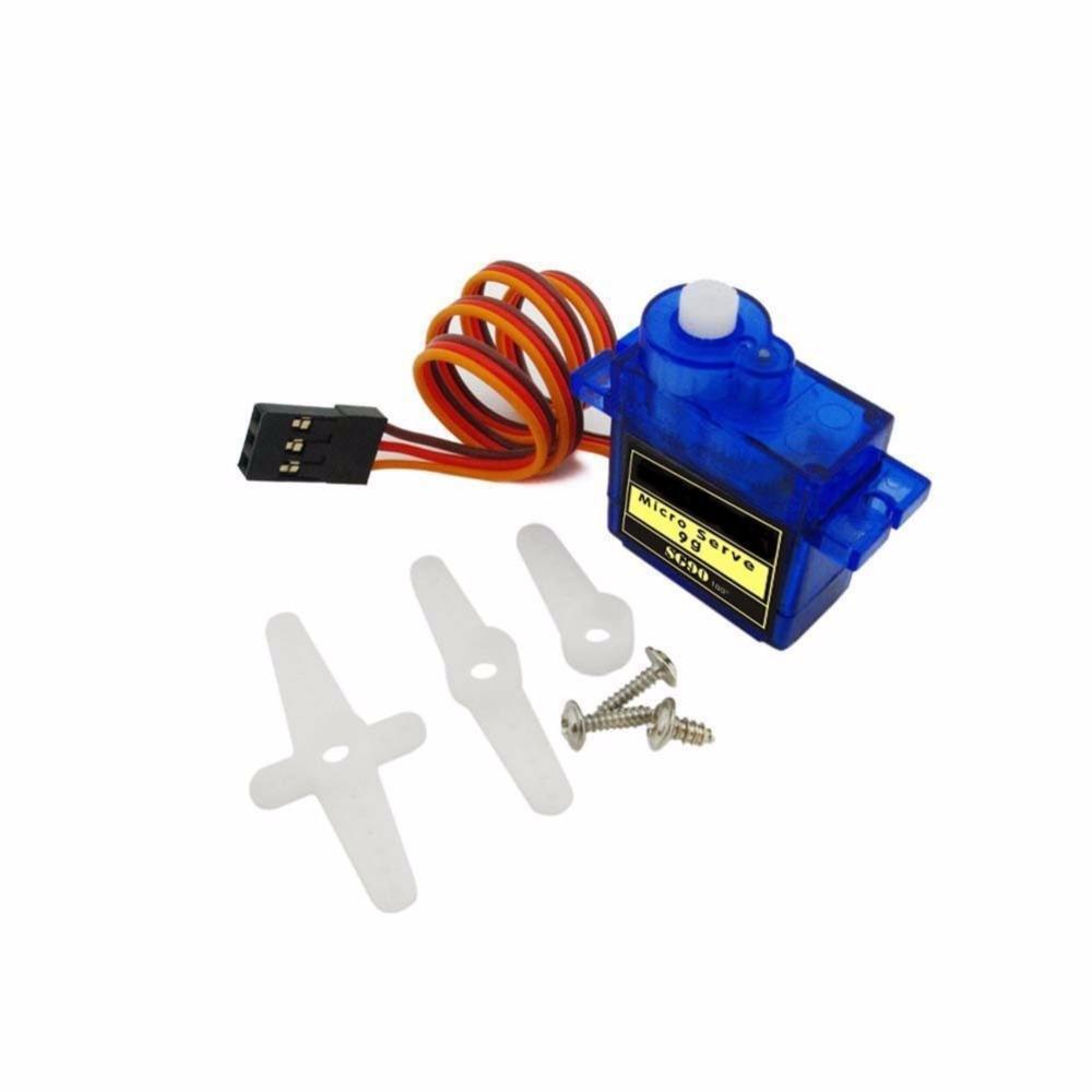
(2) Principle of the Servo Motor: The control signal enters the signal modulation chip from the receiver’s channel, obtaining a DC bias voltage. It has an internal reference circuit that generates a reference signal with a period of 20ms and a width of 1.5ms. The obtained DC bias voltage is compared with the voltage of the potentiometer to obtain the voltage difference output. Finally, the polarity of the voltage difference is output to the motor driver chip to determine the motor’s forward or reverse rotation. When the motor speed is constant, the potentiometer rotates by cascading reduction gears, causing the voltage difference to be zero and the motor to stop rotating. Of course, we don’t need to understand its specific working principle, knowing its control principle is enough. Just like using a transistor, knowing that it can be used as a switch or amplifier, we don’t need to consider how the electrons flow inside the transistor.
The servo motor wiring diagram is shown in the following image: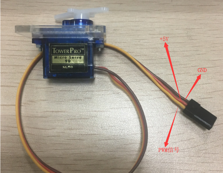
Hardware Connection
For this experiment, we used an Arduino Uno, a potentiometer, a servo motor, and several wires. The circuit connection diagram is shown below: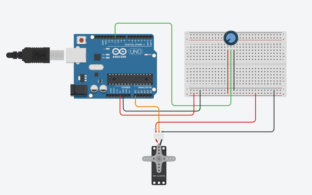
The demonstration of this experiment is as follows:
Arduino Code
The code for this experiment is as follows:
1 | |
2 Displaying Distance Data from Ultrasonic Sensor on LCD Screen
This experiment combines an ultrasonic sensor with an LCD screen to measure the distance from the module to obstacles, and display this distance on the LCD screen.
Hardware Connection
- Ultrasonic Sensor
(1) The principle of ultrasonic distance measurement is based on the time difference between the transmitter emitting ultrasonic waves and the receiver receiving them, similar to the principle of radar ranging. The ultrasonic transmitter emits ultrasonic waves in a certain direction and starts timing at the moment of emission. The ultrasonic waves propagate through the air and immediately return when they encounter an obstacle. The ultrasonic receiver stops timing when it receives the reflected wave.
(2) Measurement principle:
a. Using a timer, when the echo pin of our ultrasonic module transitions from low to high, we start the timer.
b. When the echo pin of our ultrasonic module transitions back to low, it indicates the end, i.e., stop the timer.
c. Applying the formula: Distance = (Speed (340m/s) * Time) / 2
The ultrasonic sensor pinout is shown in the following image: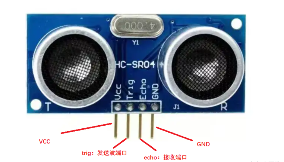
- LCD Screen
The LCD screen is one of the simplest devices used to display the output of Arduino projects. There are two different types of LCDs: graphic and character dot matrix LCDs. We will be using a character LCD here. The pinout of the LCD screen is as follows: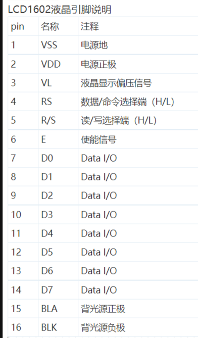
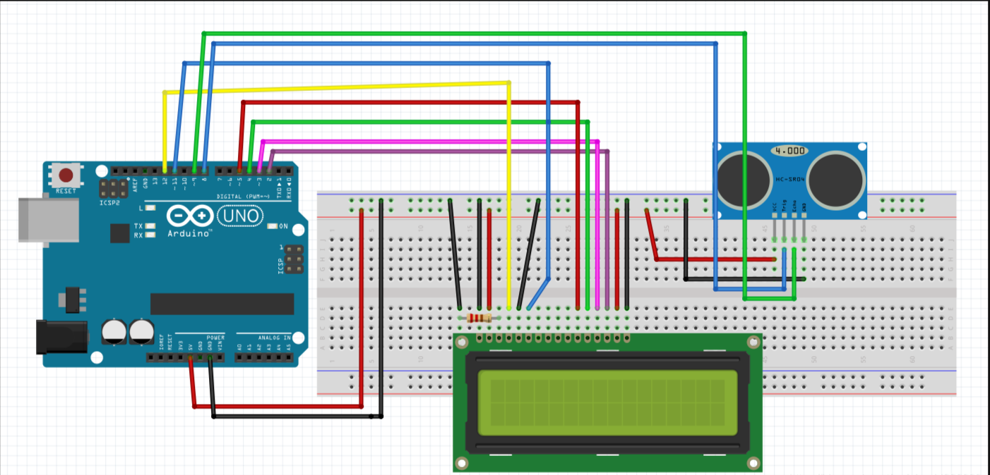
- For this experiment, we will be using an Arduino Uno, an LCD screen, an ultrasonic sensor, and several wires. The circuit connection diagram is shown below:
The demonstration of this experiment is as follows: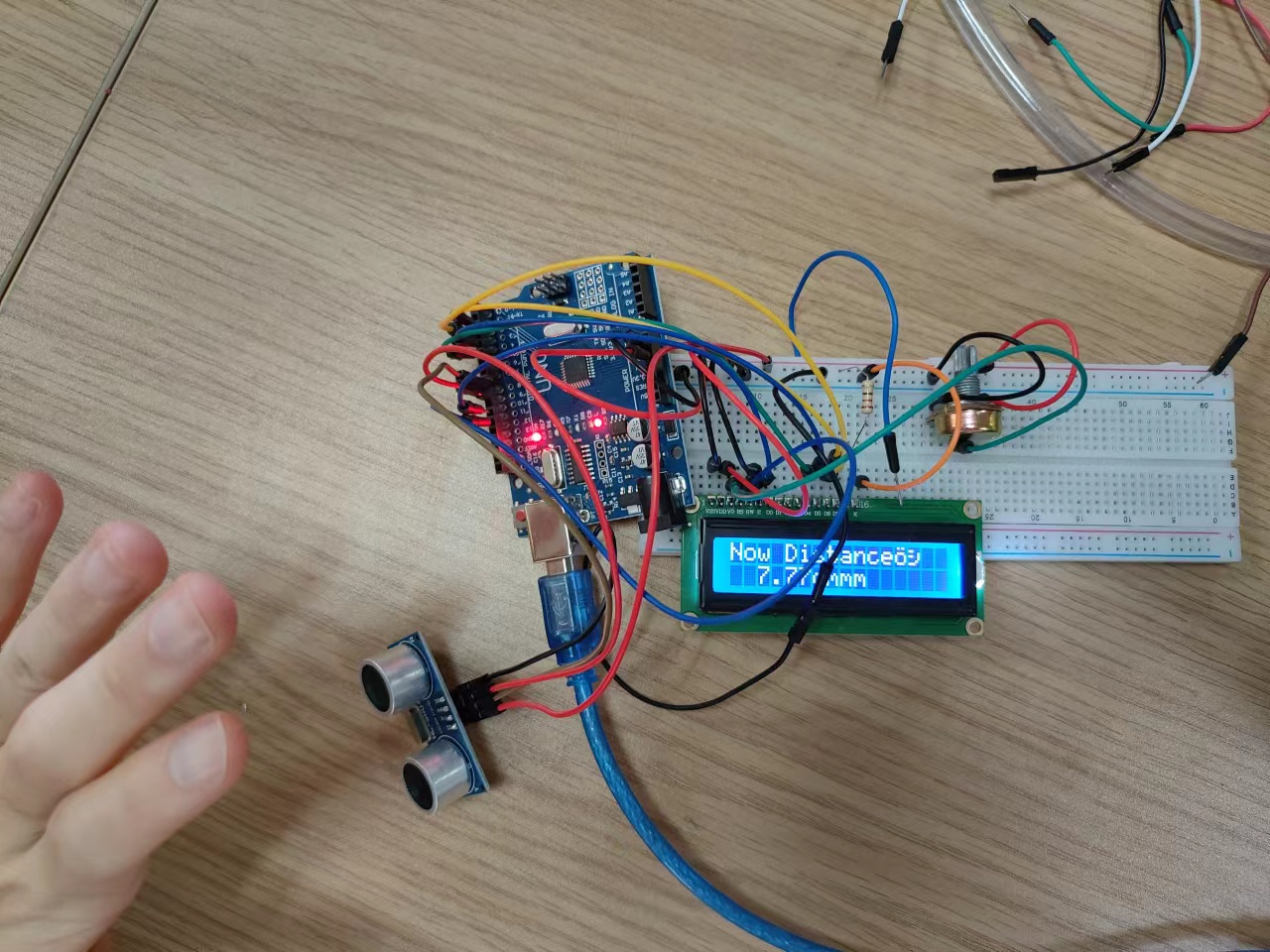
Arduino Code
The code for this experiment is as follows:
1 | |
3 Controlling 8x8 Common Cathode Red LED Matrix with Arduino
In this experiment, an 8x8 common cathode red LED matrix is used. The first part of the experiment involves displaying a small heart shape on the screen using code. The second part displays text and a blinking heart on the screen.
Hardware Connection
- 8x8 Common Cathode Red LED Matrix
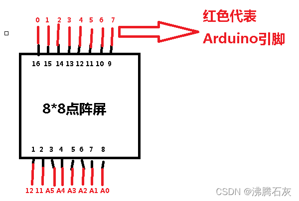
The red LED matrix has a total of 16 pins. These pins represent 8 columns and 8 rows. By specifying which column and row pins have a high or low voltage level, you can control which LEDs are lit up. For example, to light up the top-left LED, you need to set the column pin 13 to a high voltage level and the row pin 9 to a low voltage level. You can use a multimeter to test the circuit continuity and verify the LED lighting.
The schematic diagram and circuit connection of the components are shown in the following figures: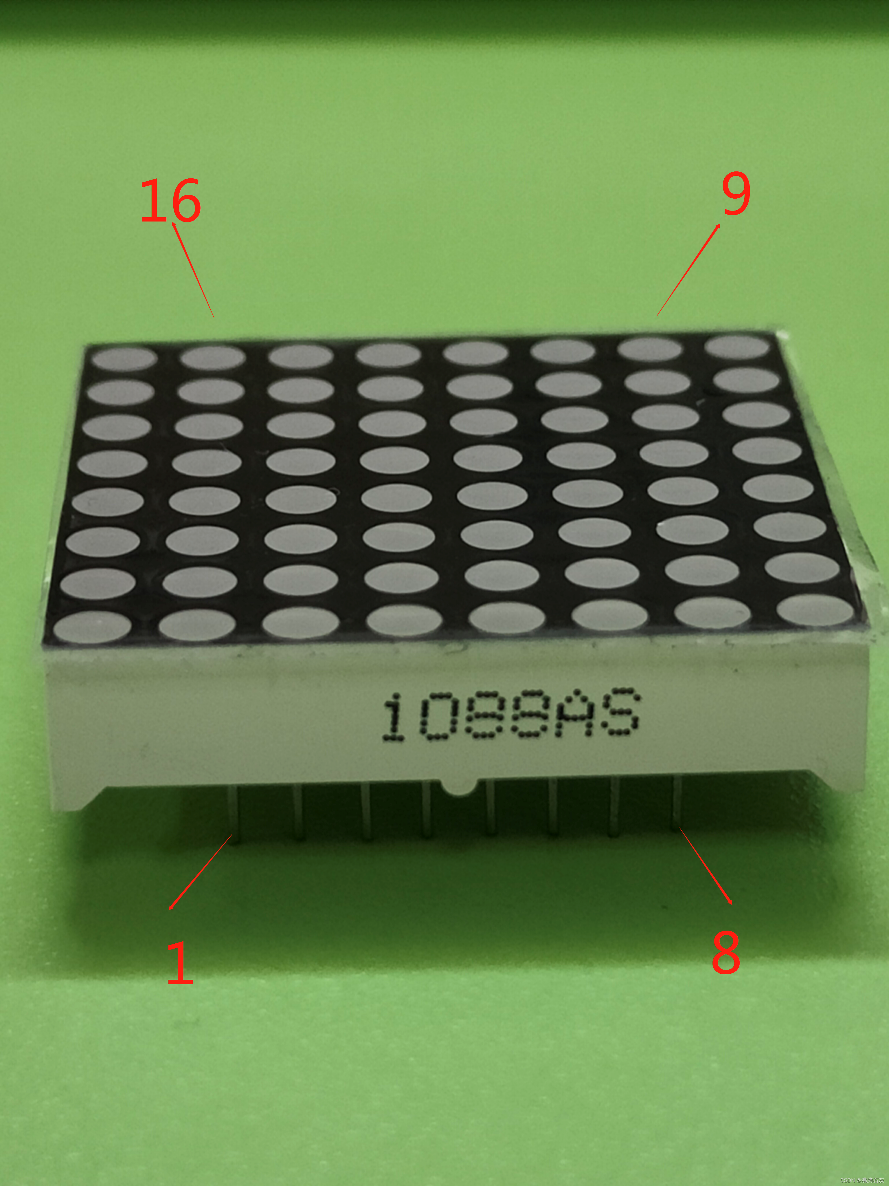
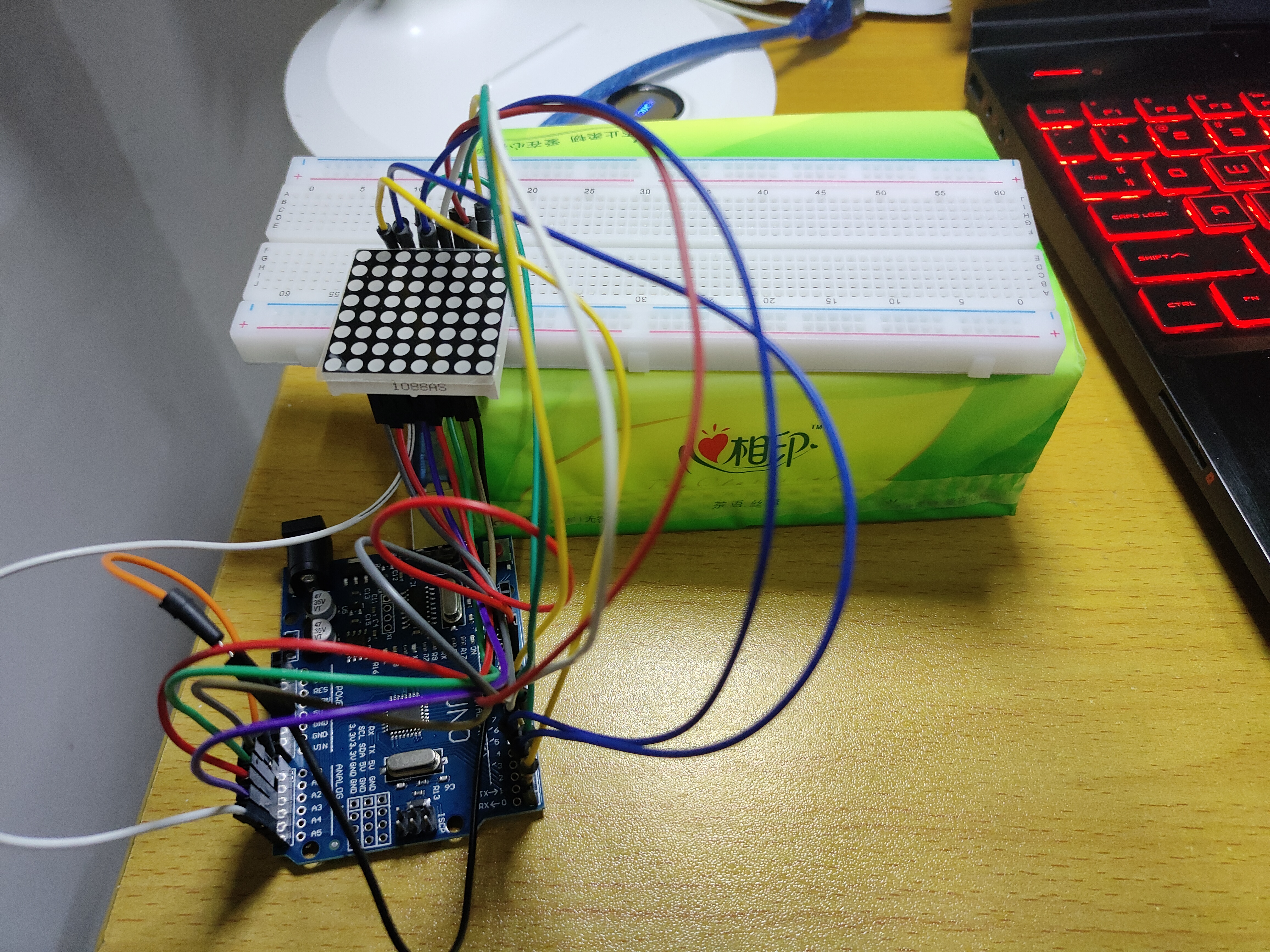
- For this experiment, you will need an Arduino Uno, an 8x8 common cathode red LED matrix, a breadboard, and several jumper wires. The hardware connection is shown in the following figure (the component is not available in Tinkercad):
Arduino Code
- The first experiment is to light up a heart on the screen. The actual effect is shown below:
The code for this experiment is shown below: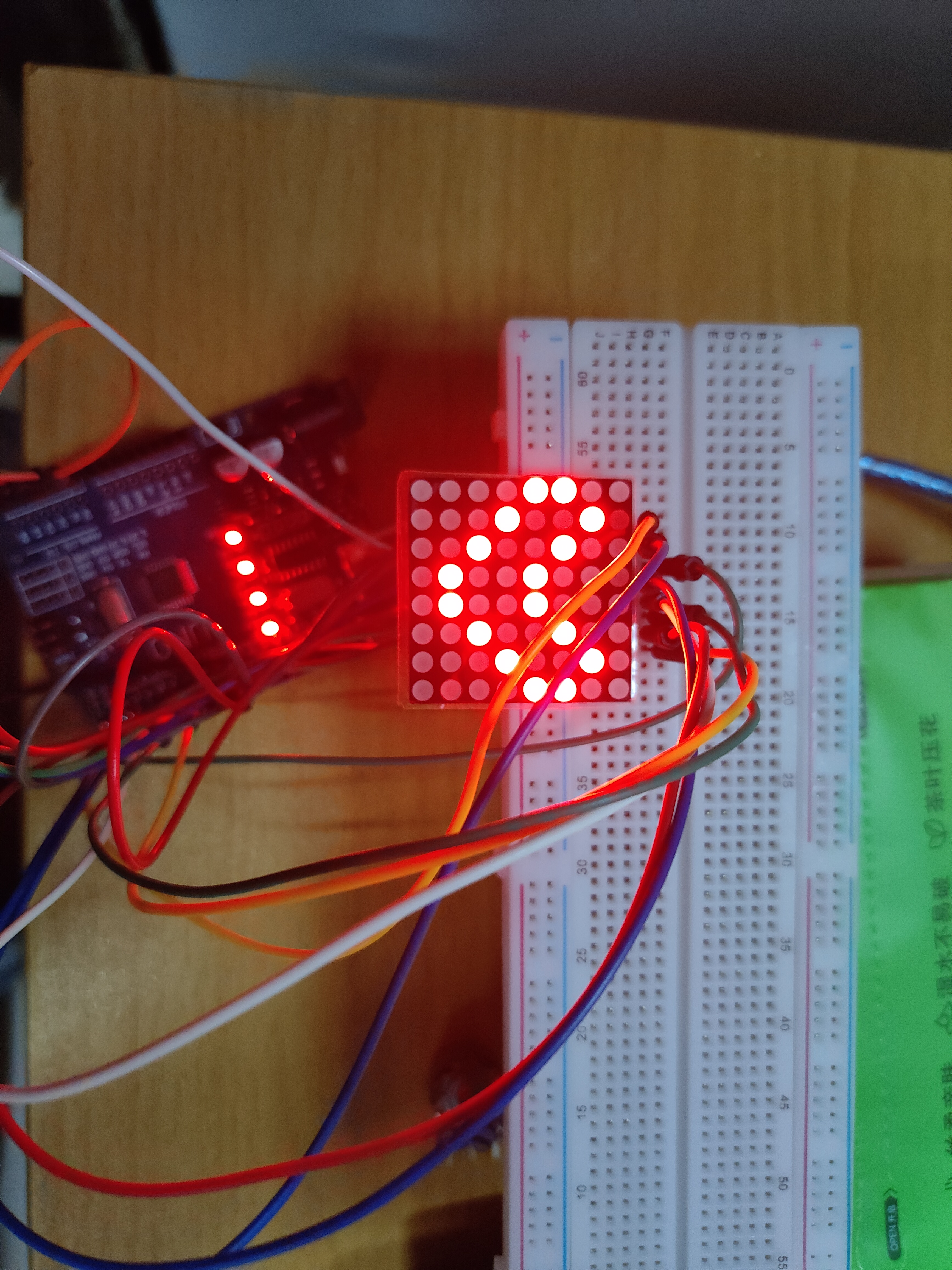
1 | |
- The second experiment is to display the text “祝大家节日快乐” (Wishing everyone a happy holiday) on the screen, along with a blinking heart. The actual effect is shown below:
The code for this experiment is shown below:
1 | |
Reference article link for this section: